Samsung S3F401F User Manual
Page 263
S3F401F_UM_REV1.00
UART
12-25
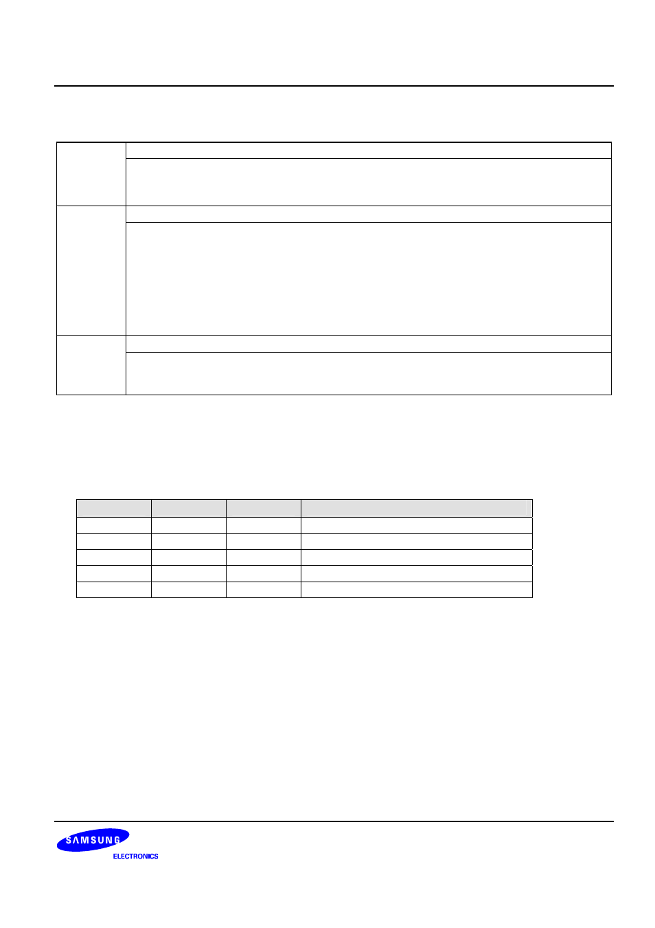
UART Line Control Clock Register (Continued) UARTLCR_H (0x02C)
Access: Read/Write
FEN
Enable FIFO Mode
1: FIFO mode, transmit and receive FIFO buffers are enabled
0: Non-FIFO mode, character mode, the FIFO are disabled
The FIFO .become 1byte-deep holding registers.
WLEN Word
Length
The word length indicates the number of data bits to be transmitted or received per frame.
00 = 5-bits 01 = 6-bits
10 = 7-bits 11 = 8-bits
the number of data bits transmitted or received in a frame
11 = 8 bits
10 = 7 bits
01 = 6 bits
00 = 5 bits
SPS
Stick Parity Select
When bits 1,2 and 7 of the UARTLCR_H register are set, the parity bit is transmitted and
checked as a 0. When bits 1 and 7 are set, and bit 2 is 0, the parity bit is transmitted and
checked as a 1. When this bit is cleared stick parity is disabled.
NOTES:
1. To update the three registers there are two possible sequences:
− UARTIBRD write, UARTFBRD write and UARTLCR_H write
− UARTFBRD write, UARTIBRD write and UARTLCR_H write
To update UARTIBRD or UARTFBRD only:
− UARTIBRD write (or UARTFBRD write) and UARTLCR_H write
2. Truth table for the SPS, EPS and PEN bits of the UARTLCR_H register
PEN
EPS
SPS
Parity Bit (transmitted or checked)
0
x
x
Not transmitted or checked
1
1
0
Even parity
1
0
0
Odd parity
1 0 1
1
1 1 1
0
3. The baud rate and line control registers must not be changed:
− When the UART is enabled.
− When completing a transmission or a reception when it has been programmed to become disabled.
The FIFO integrity is not guaranteed under the following conditions:
− after the BRK bit has been initiated
− if the software disables the UART in the middle of a transmission with data in the FIFO, and then
re-enables it.
LINE CONTROL REGISTER (UARTLCR_H)
This register accesses bits 29 to 22 of the URT bit rate and line control register, UARTLCR.
UARTLCR_H, UARTIBRD and UARTFBRD form a single 30-bit wide register(UARTLCR) which is updated
on a single write strobe generated by a UARTLCR_H write. So, in order to internally update the contents of
UARTIBRD or UARTFBRD, a UARTLCR_H write must always be performed at the end.