Siemens Simatic S7-400 User Manual
Page 420
Cable Duct and Fan Subassemblies
9-8
S7-400, M7-400 Programmable Controllers Module Specifications
A5E00069467-07
Signaling Concept
The signaling concept of the 24 VDC fan subassembly is identical to the signaling
concept of the 120/230 VAC fan subassembly.
Fuse
Included in this fan subassembly are standard cartridge fuse links,
5 x 20 mm, conforming to DIN
•
1.0 AT for 24 V
The fuse is already installed on shipping from the factory.
Shielding Clamps
If you do not require the shielding clamps supplied, do not install them in the fan
subassembly.
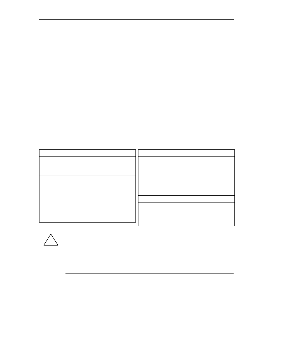
Technical Specifications
Dimensions, Weights
Dimensions WxHxD (mm)
482.5
Ч
109.5
Ч
235
(
)
Weight
appr. 2000 g
Kabeldurchmesser
3 bis 9 mm
Nominal Sizes
Lifespan of the fans
•
at
40°
C
•
at
75°
C
70000 h
25000 h
Max. contact load of relay con-
tacts 1 to 6
•
Switching voltage
•
Switching current
24 VDC
200 mA
Voltages, Currents, Potentials
Input voltage
•
Nominal value
•
Valid range
DC 24 V
Static 19.2 V up to 30
V
Dynamic: 18.5 up to
30.2 V
Starting current
0.9 A at 24 V
Fuses
1.0 AT
Power consumption
•
with fan
•
without fan
12 W
1.4 W
!
Caution
Danger of damage to equipment.
If you insert the monitoring PCB in the wrong position in the fan subassembly, the
fan subassembly may be damaged.
During maintenance of the unit, make sure you do not replace the monitoring PCB
in the wrong position.
Monitoring Function
In the case of a fault (defective fans) the fans are not switched off. Once you have
replaced the defective fan(s), the fault is acknowledged automatically as soon as
the fans have reached the required speed. Any faults that occur are not stored.
When you switch on the fan subassembly, the fans start running. After
approximately 10 s the current status of the fans is indicated via LEDs and relays.