Procedure for setting up communication, Related parameters – Yaskawa iQpump Controller Programming Manual User Manual
Page 98

98
YASKAWA
TM.iQp.07 iQpump Controller Programming Manual
Important:
• Separate the communication cables from the main circuit cables and control circuit wiring.
• Use shielded cables for the communication cable, and use proper shield clamps.
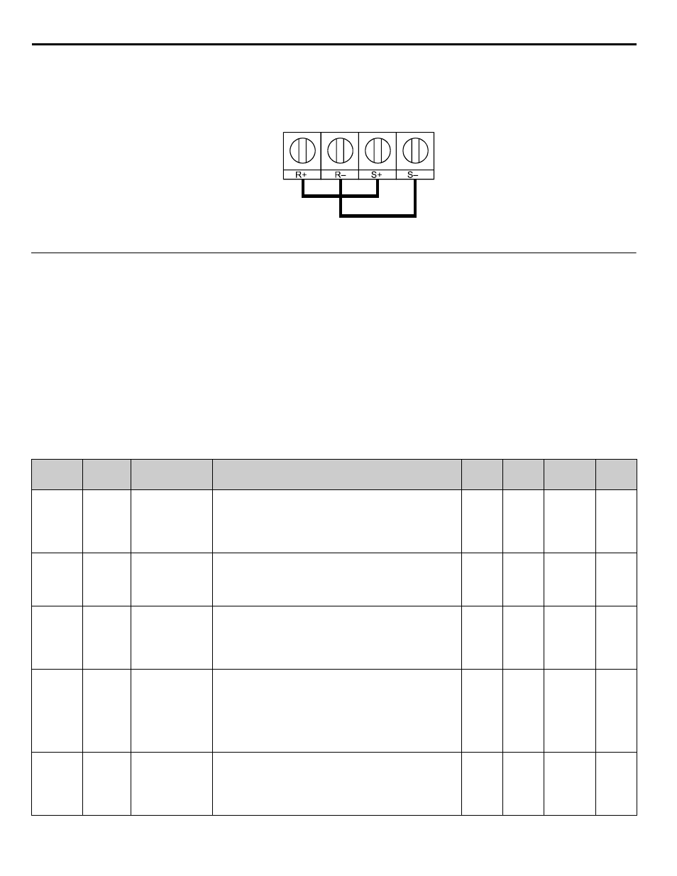
• When using RS-485 2 Wire communication, connect S+ to R+, and S- to R-, on the control circuit terminal board. See
• Terminate shield at one end only.
Figure 1.89
Figure 88.
◆
Procedure for Setting Up Communication
Use the following procedure to perform communication with the PLC.
1. Turn OFF the input power to the iQpump drive and connect the communication cable between the PLC and the drive.
2. Turn ON the input power to the drive.
3. Set the required communication parameters (H5-01 ~ H5-09) using the Digital Operator.
4. Turn OFF the input power to the drive, and check that the Digital Operator display has completely faded.
5. Turn ON the input power to the iQpump drive once again.
6. Perform communication with the PLC.
■
Related Parameters
The following parameters need to be set correctly to insure proper operation of the iQpump drive when using MEMOBUS / Modbus
communication.
Table 35 Serial Communication Related Parameters
Parameter
No.
Addr. Hex
Parameter Name
Digital Operator
Display
Description
Setting
Range
Factory
Setting
Menu
Location
Page
Number
b1-01
0108
Frequency Reference
Selection
Reference Source
Selects the speed command (frequency reference) input source.
0: Operator - Digital preset speed d1-01
1: Terminals - Analog Input Terminal A1 (or Terminal A2 see
parameter H3-13)
2: Serial Com - RS-485 terminals R+, R-, S+ and S-
3: Option PCB - Option board connected at 2CN
0 ~ 3
0
Pump Quick
Setup
b1-02
0181
Run Command
Selection
Run Source
Selects the run command input source.
0: Operator - “Hand” and “Off” keys on digital operator
1: Terminals - Contact Closure on Terminal S1
2: Serial Com - RS-485 terminals R+, R-, S+ and S-
3: Option PCB - Option board connected at 2CN
0 ~ 3
1
Pump Quick
Setup
H5-01
0425
Drive Node Address
Serial Com Adr
Selects drive station node number (address) for terminals R+, R-, S+,
S-.
Note: An address of “0” disables serial com.
Drive power must be cycled before the changes will take effect.
<0034>
*Range is dependent on P9-25, if P1-01 = 3. <0034>
0 ~ 20*
1F
Programming
H5-02
0426
Communication
Speed Selection
Serial Baud Rate
Selects the baud rate for terminals R+, R-, S+ and S-.
0: 1200 Baud
1: 2400 Baud
2: 4800 Baud (APOGEE FLN)
3: 9600 Baud (Metasys N2)
4: 19200 Baud
Note: Drive power must be cycled before the changes will take
effect. <0034>
0 ~ 4
3
Programming
H5-03
0427
Communication
Parity Selection
Serial Com Sel
Selects the communication parity for terminals R+, R-, S+ and S-.
0: No Parity
1: Even Parity
2: Odd Parity
Note: Drive power must be cycled before the changes will take
effect. <0034>
0 ~ 2
0
Programming
