L1-03 motor overheat alarm operation selection, L1-04 motor overheat fault operation selection, L1-05 motor temperature input filter time – Yaskawa iQpump Controller Programming Manual User Manual
Page 115
YASKAWA TM.iQp.07 iQpump Controller Programming Manual
115
Figure 1.93
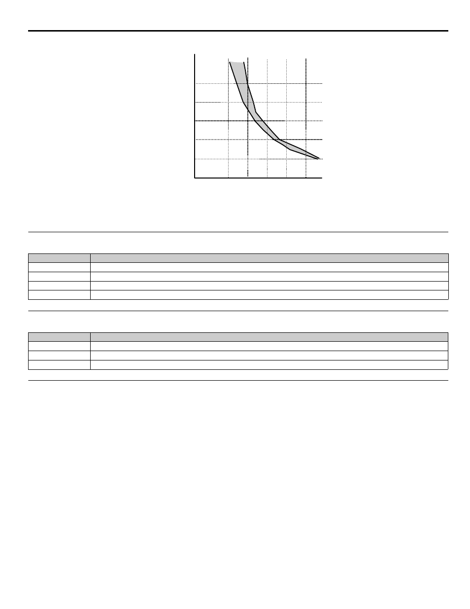
Figure 97. Motor Overload Protection Time based on Output frequency and Load
◆
L1-03 Motor Overheat Alarm Operation Selection
◆
L1-04 Motor Overheat Fault Operation Selection
◆
L1-05 Motor Temperature Input Filter Time
Setting Range:
0.00 ~ 10.00 s
Factory Default: 0.20 s
The iQpump drive can be programmed to accept a PTC (Positive Temperature Coefficient) Thermistor input for monitoring motor
temperature. By setting parameter H3-09 = “E: Motor Temperature,” and attaching the PTC thermistor per the
below, the
iQpump drive can react to the increasing motor winding temperature with both an alarm (L1-03) and a fault (L1-04).
Setting
Description
0
Ramp to Stop
1
Coast to Stop
2
Fast-Stop
3
Alarm Only (
factory default
)
Setting
Description
0
Ramp to Stop
1
Coast to Stop (
factory default
)
2
Fast-Stop
125%
4
2
Time
(M
inut
es
)
Output Current
(Percent of motor FLA)
E2-01 200%
6
8
10
60Hz
10Hz
175%
150%
- Tag Generator (30 pages)
- MP3300iec (82 pages)
- 1000 Hz High Frequency (18 pages)
- 1000 Series (7 pages)
- PS-A10LB (39 pages)
- iQpump Micro User Manual (300 pages)
- 1000 Series Drive Option - Digital Input (30 pages)
- 1000 Series Drive Option - CANopen (39 pages)
- 1000 Series Drive Option - Analog Monitor (27 pages)
- 1000 Series Drive Option - CANopen Technical Manual (37 pages)
- 1000 Series Drive Option - CC-Link (38 pages)
- 1000 Series Drive Option - CC-Link Technical Manual (36 pages)
- 1000 Series Drive Option - DeviceNet (37 pages)
- 1000 Series Drive Option - DeviceNet Technical Manual (81 pages)
- 1000 Series Drive Option - MECHATROLINK-II (32 pages)
- 1000 Series Drive Option - Digital Output (31 pages)
- 1000 Series Drive Option - MECHATROLINK-II Technical Manual (41 pages)
- 1000 Series Drive Option - Profibus-DP (35 pages)
- AC Drive 1000-Series Option PG-RT3 Motor (36 pages)
- Z1000U HVAC MATRIX Drive Quick Start (378 pages)
- 1000 Series Operator Mounting Kit NEMA Type 4X (20 pages)
- 1000 Series Drive Option - Profibus-DP Technical Manual (44 pages)
- CopyUnitManager (38 pages)
- 1000 Series Option - JVOP-182 Remote LED (58 pages)
- 1000 Series Option - PG-X3 Line Driver (31 pages)
- SI-EN3 Technical Manual (68 pages)
- JVOP-181 (22 pages)
- JVOP-181 USB Copy Unit (2 pages)
- SI-EN3 (54 pages)
- SI-ET3 (49 pages)
- MECHATROLINK-III (35 pages)
- EtherNet/IP (50 pages)
- SI-EM3 (51 pages)
- 1000-Series Option PG-E3 Motor Encoder Feedback (33 pages)
- 1000-Series Option SI-EP3 PROFINET (56 pages)
- PROFINET (62 pages)
- AC Drive 1000-Series Option PG-RT3 Motor (45 pages)
- SI-EP3 PROFINET Technical Manual (53 pages)
- A1000 Drive Option - BACnet MS/TP (48 pages)
- 120 Series I/O Modules (308 pages)
- A1000 12-Pulse (92 pages)
- A1000 Drive Software Technical Manual (16 pages)
- A1000 Quick Start (2 pages)
- JUNMA Series AC SERVOMOTOR (1 page)
- A1000 Option DI-101 120 Vac Digital Input Option (24 pages)