Yaskawa iQpump Controller Programming Manual User Manual
Page 100
100
YASKAWA
TM.iQp.07 iQpump Controller Programming Manual
Function Code
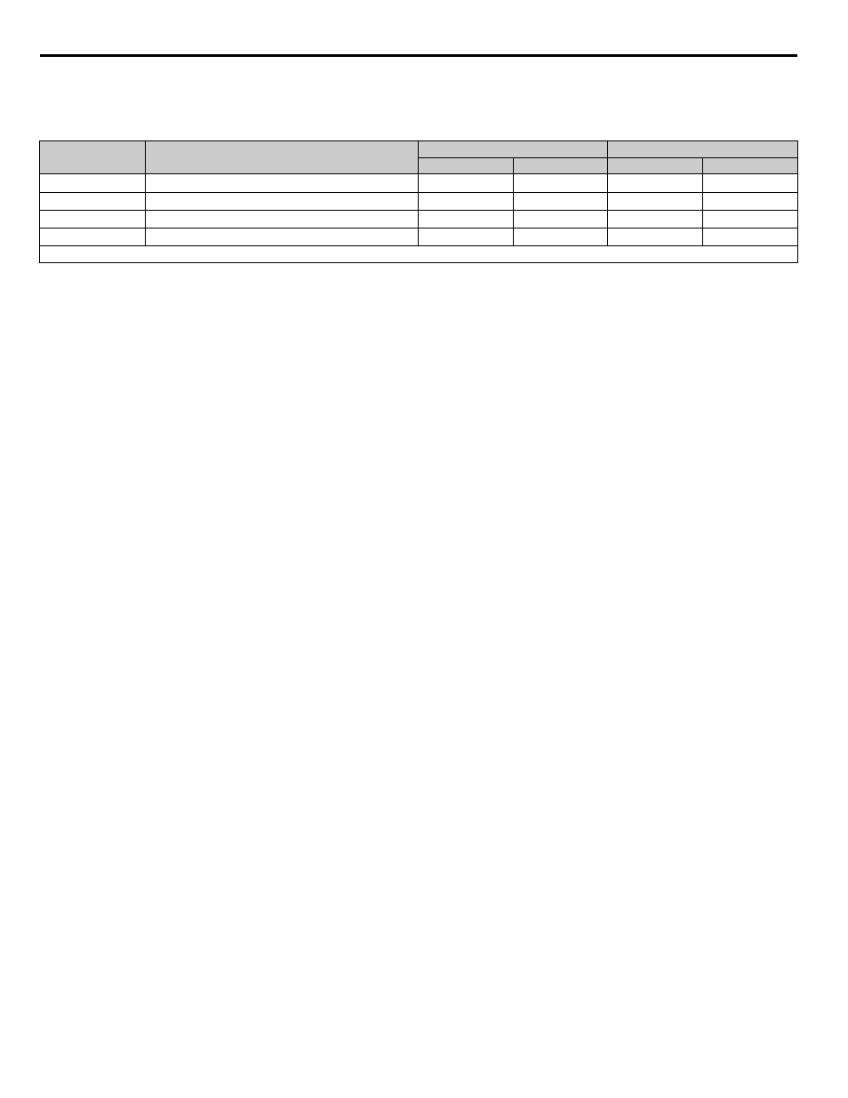
The function code specifies commands. There are four function codes supported by the drive, as shown below.
Table 36 MEMOBUS / Modbus Function Codes
Data
Configure consecutive data by combining the storage register address (test code for a loopback address) and the data the register contains.
The data length changes depending on the command details.
Error Check
Errors are detected during communication using CRC-16. Perform calculations using the following method:
1. The factory setting for CRC-16 communication is typically zero, but when using the MEMOBUS / Modbus system, set the factory
setting to one (e.g., set all 16 bits to 1).
2. Calculate CRC-16 using MSB as slave address LSB, and LSB as the MSB of the final data.
3. Calculate CRC-16 for response messages from the slaves and compare them to the CRC-16 in the response messages.
Function Code
(Hexadecimal)
Function
Command Message
Response Message
Min. (Bytes)
Max. (Bytes)
Min.* (Bytes)
Max. (Bytes)
03H
Reading / Holding Register Contents
8
8
7
37
06H
Write In Single Holding Register
8
8
8
8
08H
Loopback Test
8
8
8
8
10H
Write In Several Holding Registers
11
41
8
8
* Minimum bytes for a normal Response Message (error response message is always 5 bytes).