Yaskawa iQpump Controller Programming Manual User Manual
Page 252

252
YASKAWA
TM.iQp.07 iQpump Controller Programming Manual
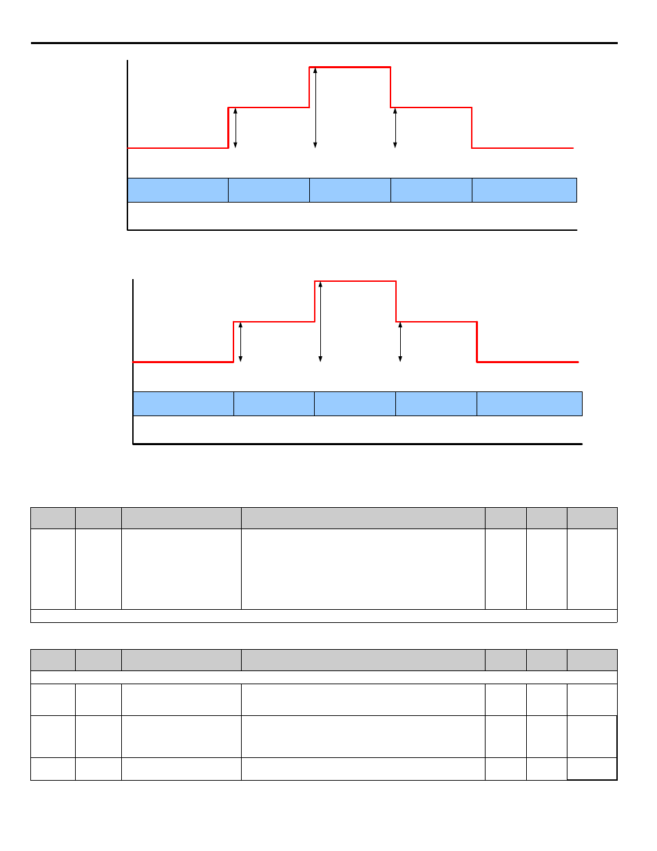
Figure 1.188
Figure 192. Setpoint Modifier P9-17
Figure 1.189
Figure 193. Network Start Delay P9-29
Table 118 Related Parameters
Table 119 Parameters
Parameter
No.
Addr.
Hex
Parameter Name
Digital Operator Display
Description
Range
Default
Menu
Location
P1-09
608
High Feedback Level
High FB Level
System will show alarm (HFB) when feedback level rises above the
programmed level. The alarm will turn off when the feedback level
falls below the programmed High Feedback Level minus the
Hysteresis Level (P1-13)
This function is active during running in Hand Mode, Auto Mode,
Pre-charge and Thrust bearing Mode. If P1-01 = 3, parameter P9-18
uses this value to calculate the quick de-stage feedback level.
0 ~ 6000.0
(system
units
P1-02)
155.0
(system
units
P1-02)
Programming
Denotes that parameter can be changed when the drive is running.
Parameter
No.
Addr.
Hex
Parameter Name
Digital Operator Display
Description
Range
Default
Menu
Location
Parameter functionality stated below only applies when P1-01 = 3 (MEMOBUS / Modbus Network)
P9-01
0880
Lead Drive Selection
Lead Drive Sel
Specifies how the next Lead drive is selected.
0: Next Available
1: Lowest Run-time
0 ~ 1
1
Programming
P9-05
0884
Lag Drive Mode
Lag Drive Mode
Determines how the lag drives function.
0: Fixed Speed: Runs at the P9-06 setting.
1: PI Regulation: Uses PI to determine speed.
2: Turn Off drive stops running when it switches to a lag drive.
0 or 2
0
Programming
P9-06
0885
Lag Fixed Speed
Lag Fixed Speed
When the drive changes from a lead to a lag and P9-05 = 0, the drive
will run at this speed after P9-07 delay time expires.
0.0 ~
120.0 Hz
55.0 Hz Programming
Time
Set-Point
1
2
3
2
1
# of Pumps
Running
Set-Point Modifier
(P9-17) x 1
Set-Point Modifier
(P9-17) x 1
Set-Point Modifier
(P9-17) x 2
Time
Set-Point
1
2
3
2
1
# of Pumps
Running
Set-Point Modifier
(P9-17) x 1
Set-Point Modifier
(P9-17) x 1
Set-Point Modifier
(P9-17) x 2
