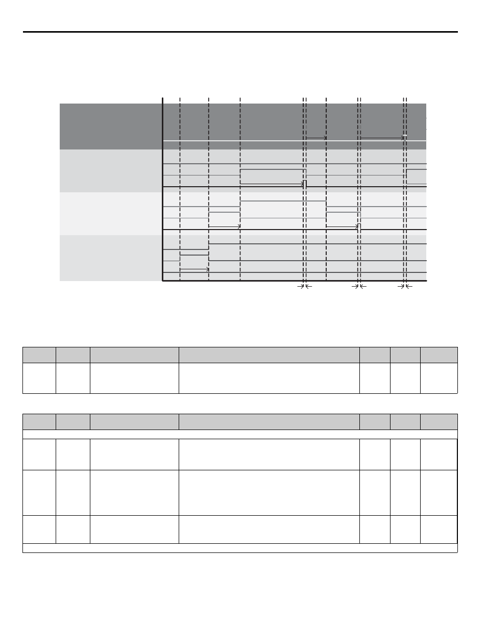
Figure 181. alternation mode is lifo, Drive 1 drive 2 drive 3, Drive 4 – Yaskawa iQpump Controller Programming Manual User Manual
Page 238

238
YASKAWA
TM.iQp.07 iQpump Controller Programming Manual
Figure 1.177
Figure 181. Alternation Mode is LIFO
Table 114 Related Parameters
Table 115 Parameters
Parameter
No.
Addr.
Hex
Parameter Name
Digital Operator Display
Description
Setting
Range
Factory
Setting
Menu
Location
P9-01
0880
Lead Drive Selection
Lead Drive Se
l
Specifies how the next Lead Drive is selected:
0: Next Available
1: Lowest Runtime
0 ~ 1
0
Programming
Parameter
No.
Addr.
Hex
Parameter Name
Digital Operator Display
Description
Setting
Range
Factory
Setting
Menu
Location
Parameter functionality stated below only applies when P1-01 = 3 (MEMOBUS / Modbus Network)
P9-03
0882
Alternation Time
Alternation Time
Specifies the time for a drive to request alternation, influenced by the
Alternation Mode P9-04.
The alternation feature is disabled when the parameter is set to 0.
0 ~ 1000 H
24 H
Programming
P9-04
0883
Alternation Mode
Alternation Mode
Determines how alternation is performed:
0: FIFO Auto
1: FIFO Forced
2: LIFO
3: FIFO @ Sleep
0 ~ 3
0
Programming
P9-19
0892
Alternation Unit
Alternation Unit
Selects the unit for P9-03
0: Hours (hr)
1: Minutes (min)
0 ~ 1
0
Programming
Denotes that parameter can be changed when the drive is running.
PumpNet Control 1 U1-xx bit 1:
Run as Lag Drive
PumpNet Control 1 U1-xx bit 2:
Run as Lead Drive
PumpNet Control 1 U1-xx bit 1:
Run as Lag Drive
PumpNet Control 1 U1-xx bit 2:
Run as Lead Drive
-
PumpNet Control 1 U1-xx bit 1:
Run as Lag Drive
PumpNet Control 1 U1-xx bit 2:
Run as Lead Drive
Drive 1
Drive 2
Drive 3
Alternation
Timer 10H
PumpNet Status 1 U1-xx bit 6:
Request for LIFO Alternation
PumpNet Status 1 U1-xx bit 6:
Request for LIFO Alternation
PumpNet Control 1 U1-xx bit 1:
Run as Lag Drive
PumpNet Control 1 U1-xx bit 2:
Run as Lead Drive
Drive 4
PumpNet Status 1 U1-xx bit 6:
Request for LIFO Alternation
PumpNet Status 1 U1-xx bit 6:
Request for LIFO Alternation
-
Alternation Timer 24H
Network
Processing
& Delay
Network
Processing
& Delay
Drive 1 is the
Lead Drive…
starts the
timer.
Alternation
Timer 12H
P9-03 = 24H
Alternation
Timer 8H
Alternation
Timer 12H
Alternation Timer 16H
Network
Processing
& Delay
Drive 2 is the
Lead Drive…
starts the
timer.
Drive 1
pauses the
timer at 10H.
Drive 3 is the
Lead Drive…
starts the
timer.
Drive 2
pauses the
timer at 12H.
Drive 3 alternation
timer expires,
requests for a new
lead and gets
removed from the
system.
Drive 4 is the
Lead Drive…
starts the timer.
System demand
is low, and
Drive 3 is
removed from
the system by
the Multiplex
function.
Drive 2 resumes
counting from
where it left off.
Drive 2 alternation
timer expires,
requests for a new
lead and gets
removed from the
system.
Drive 4 is the
Lead Drive…
resumes counting
from where it left off.
Drive 4 alternation
timer expires,
requests for a new
lead and gets
removed from the
system.
Drive 3 is the
Lead Drive…
starts the timer.
0
0
0
0
12
10
12
24
24
24
0
8
8
