Yaskawa iQpump Controller Programming Manual User Manual
Page 277
YASKAWA TM.iQp.07 iQpump Controller Programming Manual
277
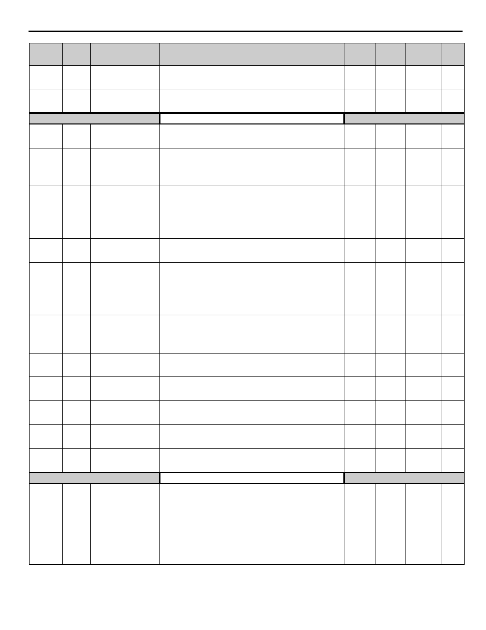
o1-07
0518
Second Line User
Monitor Selection
2nd Monitor Sel
Sets the “U1” monitor always displayed on the 4th line of the digital
operator display. Effective only when o1-06 = 1.
1 ~ 94
2
Programming
o1-08
0519
Third Line User Monitor
Selection
3rd Monitor Sel
Sets the “U1” monitor always displayed on the 5th line of the digital
operator display. Effective only when o1-06 = 1.
1 ~ 94
91
Programming
Key Selections
o2-01
0505
Local / Remote Key
Function Selection
Local/Remote Key
Has no function when HOA operator is connected.
0: Disabled
1: Enabled
0 ~ 1
1
Programming
o2-02 0506
OFF Key Function
During Auto Run
Oper OFF Key
Determines if the off key on the digital operator will stop the drive
when drive is operating from external terminals or serial
communications.
0: Disabled
1: Enabled
0 ~ 1
1
Programming
o2-03
0507
User Parameter Default
Value
User Defaults
Allows storing of current parameter values as a User Initialization
Selection at parameter A1-03.
0: No Change (No user parameter set active).
1: Set Defaults (Saves current parameter settings as user initialization.
A1-03 now allows selecting <1110> for user initialization.
2: Clear All (Clears the currently saved user initialization. A1-03 no
longer allows selecting <1110>.
0 ~ 2
0
Programming
o2-04
0508
Drive / kVA Selection
Inverter Model #
Sets the kVA of the drive. Enter the number based on drive model #.
Use the
portion of the CIMR-P7
-107 Model
Number.
0 ~ FF
kVA
Dependent
Programming
o2-05
0509
Frequency Reference
Setting
Method Selection
Operator M.O.P.
Determines if the Data / Enter key must be used to input a frequency
reference from the digital operator.
0: Disabled - Data / Enter key must be pressed to enter a frequency
reference.
1: Enabled: -Data / Enter key is not required. The frequency reference
is adjusted by the up and down arrow keys on the digital operator
without having to press the data / enter key.
0 ~ 1
0
Programming
o2-06
050A
Operation Selection
when Digital Operator is
Disconnected
Oper Detection
Determines if the drive will stop when the digital operator is removed.
0: Disabled - The drive will not stop when the digital operator is
removed.
1: Enabled - The drive will fault (OPR) and coast to stop when the
operator is removed.
0 ~ 1
1
Programming
o2-07
050B
Cumulative Operation
Time Setting
Elapsed Time Set
Sets the initial value of the elapsed operation timer.
0 ~
65535 hr
0 hr
Programming
o2-08
050C
Cumulative Operation
Time Selection
Elapsed Time Run
Sets how time is accumulated for the elapsed timer (o2-07).
0: Power-On Time (Time accumulates whenever drive is powered).
1: Running Time (Time accumulates only when drive is running)
0 ~ 1
1
Programming
o2-10
050E
Cumulative Cooling Fan
Operation Time Setting
Fan ON Time Se
t
Sets the initial value of the heatsink fan operation time.
0 ~
65535 hr
0 hr
Programming
o2-12
0510
Fault Trace / Fault
History Clear Function
FLT Trace Ini
t
Clears the fault memory contained in the U2 and U3 monitors.
0: Disabled (no effect).
1: Enabled - resets U2 and U3 monitors, and returns o2-12 to zero.
0 ~ 1
0
Programming
o2-14
0512
kWh User Monitor (U1-
29) Initialization
kWh MonitorClear
Used to reset the kilowatt Hour monitor to zero
0: Disabled (no change)
1: Clear all - Resets U1-29 to zero and returns o2-14 to zero.
0 ~ 1
0
Programming
Copy Function
o3-01
0515
Copy Function Selection
Copy Function Sel
This parameter controls the copying of parameters to and from the
digital operator.
0: COPY SELECT (no function)
1: INV -> OP READ - All parameters are copied from the drive to the
digital operator.
2: OP -> INV WRITE - All parameters are copied from the digital
operator into the drive.
3: OP <--> INV VERIFY - Parameter settings in the drive are
compared to those in the digital operator.
Note:
When using the copy function, the drive model number and
software number (U1-14) must match or an error will occur.
0 ~ 3
0
Programming
Parameter
No.
Addr.
Hex
Parameter Name
Digital Operator
Display
Description
Setting
Range
Factory
Setting
Menu
Location
Page
No.