Yaskawa iQpump Controller Programming Manual User Manual
Page 215
YASKAWA TM.iQp.07 iQpump Controller Programming Manual
215
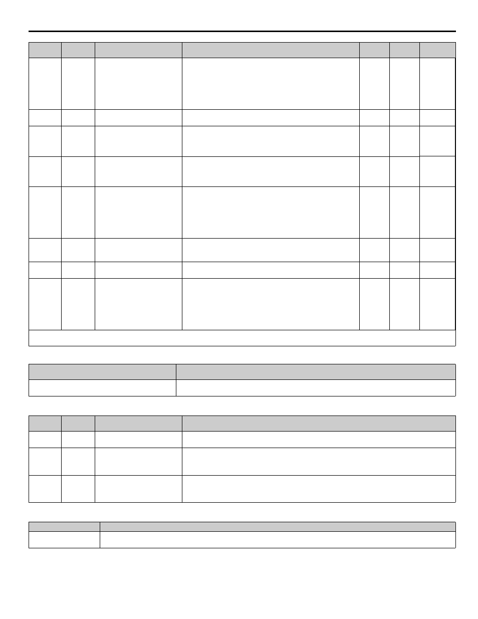
Table 90 Function Text
Table 91 Monitors
<0034>
Table 92 Multi-Function Input Setting (H1-xx)
<0034>
P6-07
846
Low Flow Select
Low Flow Sel
Sets the behavior of the drive when a “Low Flow” condition is
detected.
0: No Display
1: Alarm Only
2: Fault
3: Auto-Restart (time set by P6-08)
0 ~ 3
1
Programming
P6-08
847
Low Flow Auto-Restart Time
LowFlow Restrt
Sets the amount of time the drive will wait before attempting an auto-
restart of the “Low Flow” fault. Effective only when P6-07 = 3.
0.1 ~
6000.0 min 3.0 min Programming
P6-09
848
Accumulation Level Fine
Accum Lvl Fin
e
Sets the accumulated volume that will trigger the Accum Level
alarm, Accum Level fault, or Accum Level digital output. Total
Accum Level can be calculated as follows: Total Accum Level = P6-
10 * 1000 + P6-09.
0.0 ~
999.0 gal
0.0
Programming
P6-10
849
Accumulation Level Course
Accum Lvl Course
Sets the accumulated volume that will trigger the Accum Level
alarm, Accum Level fault, or Accum Level digital output. Total
Accum Level can be calculated as follows: Total Accum Level = P6-
10 * 1000 + P6-09.
0 ~
61036 kgl
0
Programming
P6-11
84A
Accumulation Behavior
Accum Behavior
Sets how the drive will respond when the accumulated volume
reaches the P6-09 and P6-10 level.
0: No Display
1: Alarm Only
2: Fault
3: Fault - Auto Flow Accum Reset
0 ~ 3
1
Programming
P6-12
84B
High Flow Level
High Flow Level
If the drive is running, and the flow goes above this level for more
than the P6-13 time, a High Flow fault or alarm will occur. A setting
of 0 disables the high flow detection.
0.0 ~
6000.0
(*n1)
0.0
Programming
P6-13
84C
High Flow Detection Delay Time
High Flow Time
Sets the amount of time the flow rate must be above the P6-12 level
before a High Flow condition is detected.
1 ~ 6000 s
10
Programming
P6-14
84D
High Flow Select
High Flow Sel
Sets the behavior of the drive when a “High Flow” condition is
detected.
0: No Display
1: Alarm Only
2: Fault
3: Auto-Restart (time set by L5-03)
0 ~ 3
1
Programming
Denotes that parameter can be changed when the drive is running.
(*n1) Displayed units are determined by parameter P6-02.
Function Number
Function Name
Digital Operator Display
P6
Flow Meter Setup
Flow Meter Setup
Monitor
No.
Addr.
Hex
Monitor Name
Digital Operator Display
Description
U1-95
725
Flow Rate
Flow Rate
Displays the flow rate, based upon the voltage present on Terminal A1 and parameters P6-01 and P6-02. A
two second 1st order filter will be applied to this monitor.
U1-96
72A
Volume Accumulated (Fine)
Volume (Fine)
Displays the volume that has been measured by terminal A1. Total volume can be calculated as follows:
Total Volume = U1-97 * 1000 + U1-96.
Value retained in EEPROM.
U1-97
72B
Volume Accumulated (Course)
Volume (Course)
Displays the volume that has been measured by terminal A1. Total volume can be calculated as follows:
Total Volume = U1-97 * 1000 + U1-96.
Value retained in EEPROM.
Setting
Description
75
Reset Accum
Closed: Volume accumulated will be reset to zero (and held at zero if digital input remains closed).
Parameter
No.
Addr.
Hex
Parameter Name
Digital Operator Display
Description
Setting
Range
Factory
Setting
Menu
Location