Yaskawa iQpump Controller Programming Manual User Manual
Page 253
YASKAWA TM.iQp.07 iQpump Controller Programming Manual
253
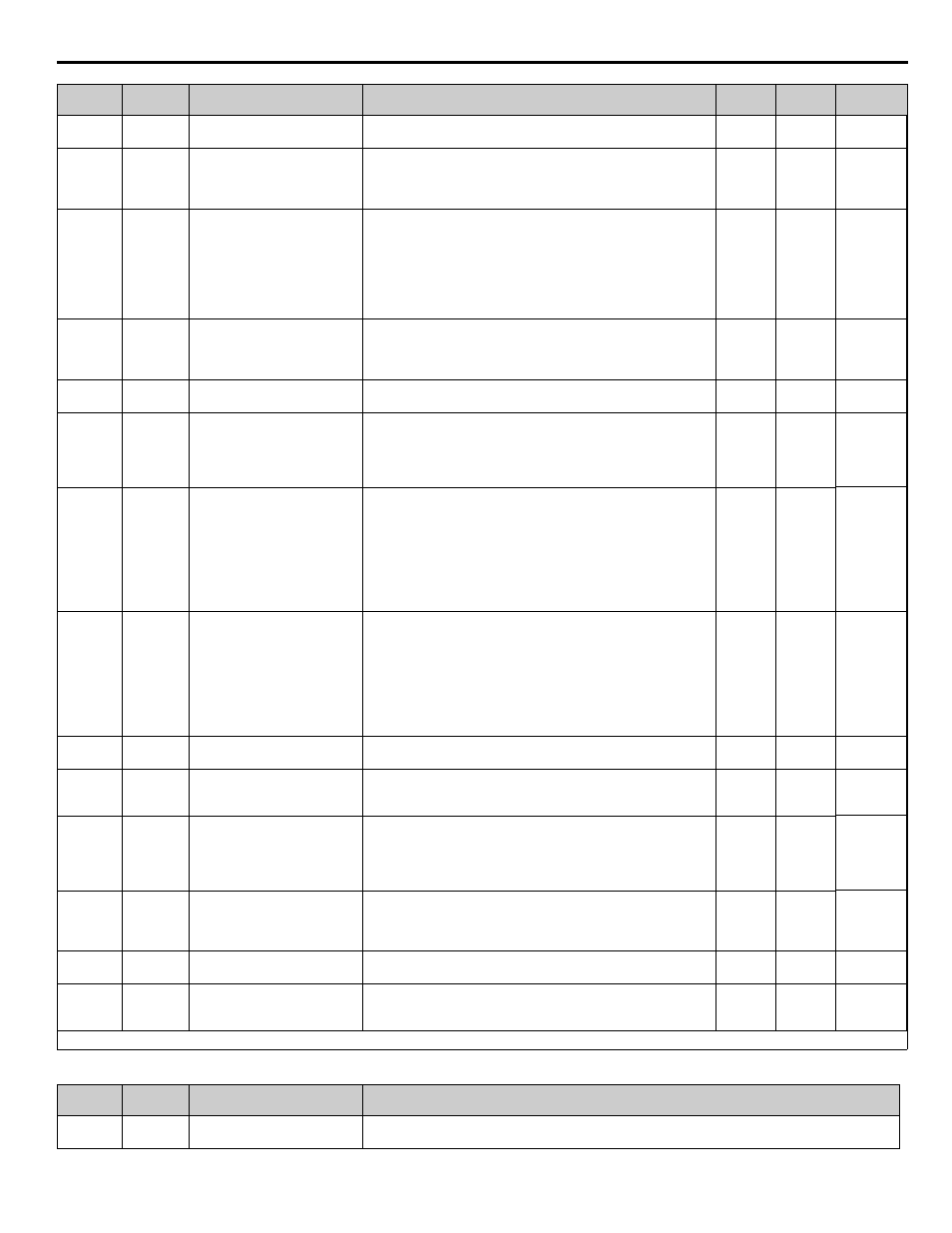
Table 120 Monitors
<0034>
P9-07
0886
Lag Fixed Speed Delay
Lag Fix Spd Dly
When the drive changes from a lead to a lag and P9-05 = 0, this time
specifies how long before the drive runs at the P9-06 speed.
0 ~
1000 s
5 s
Programming
P9-08
0887
Add Pump Mode
Add Pump Mode
Selects the detection method for staging a new pump.
0: Output Frequency
1: Feedback
2: Feedback + Fout
0 ~ 2
0
Programming
P9-09
0888
Add Freq Level
Add Freq Lvl
When P9-08 = 0 and the output frequency rises above this level for
the time set in P9-11, the lead drive will request for a new lead drive
through the iQpump MEMOBUS / Modbus network.
When P9-08 = 2 and the output frequency rises above this level and
the delta feedback (setpoint - feedback) has exceeded the level set in
P9-10 for the time set in P9-11, the lead drive will request for a new
lead drive through the iQpump MEMOBUS / Modbus network.
0.0 ~
120.0 Hz
56.0 Hz Programming
P9-10
0889
Add Delta Level
Add Delta Lvl
Sets the amount of time it will take the drive to accelerate from zero
to the De-Scale frequency reference P7-05.
(Internally limited 0.1 ~ 6000.0 s)
0 ~ 6000.0
(system
units
P1-02)
5.0
(system
units
P1-02)
Programming
P9-11
088A
Add Delay Time
Add Dly Time
Delay time before a new lead drive is added to the system.
0.~ 3600 s
10 s
Programming
P9-12
088B
Remove Pump Mode
Remove Pump Mode
Selects the detection method for de-staging to the previous lead
pump:
0: Output Frequency
1: Feedback
2: Feedback + Fout
0 ~ 2
0
Programming
P9-13
088C
Remove Freq Level
Remove Freq Lvl
When P9-12 = 0 and the output frequency is below this level for the
time set in P9-15, the lead drive will request to be removed from the
system through the iQpump MEMOBUS / Modbus network.
When P9-12 = 2 and the output frequency drops below this level and
the delta feedback (feedback - setpoint) has exceeded the level set in
P9-14 for the time set in P9-15, the lead drive will request to be
removed from the system through the iQpump MEMOBUS / Modbus
network.
0.0 ~
120.0 Hz
40.0 Hz Programming
P9-14
088D
Remove Delta Level
Remove Delta Lvl
When P9-12 = 1 and the delta feedback (feedback - setpoint) has
exceeded this level for the time set in P9-15, the lead drive will
request to be removed from the system through the iQpump
MEMOBUS / Modbus network.
When P9-12 = 2 and the delta feedback has exceeded this level and
the output frequency is below P9-13 for the time set in P9-15, the
lead drive will request to be removed from the system through the
iQpump MEMOBUS / Modbus network.
0 ~ 6000.0
(system
units
P1-02)
0.0
(system
units
P1-02)
Programming
P9-15
088E
Remove Delay Time
Remove Dly Time
Delay time before the lead drive is removed from the system.
0.~
3600 sec
10 s
Programming
P9-16
088F
Stabilization Time
Stabilize Time
Time used to stabilize the system when a pump is staged or de-
staged. Lead-lag control and pump protection is suspended during
this time.
0.~
3600 sec
3 s
Programming
P9-17
0890
Setpoint Modifier
Set-Pt Modifier
System Setpoint is incremented with this value depending on the
number of pumps running.
Pump 1: Setpoint
Pump X: Setpoint + ((X-1) (P9-17))
-6000.0 ~
6000.0
(system
units
P1-02)
0.0
(system
units
P1-02)
Programming
P9-18
0891
High Feedback Quick De-stage
High FB De-stage
Determines the feedback level to trigger a quick de-stage, set as a
percentage of parameter P1-09. The quick de-stage ignores
parameters P9-12 to P9-15 and only uses an internal 2 s delay. A
setting of 0 disables the High FB De-stage feature.
0.0 ~
100.0%
90.0%
Programming
P9-23
0896
Max Number of Running Pumps
MaxPumps Running
Limits the maximum number of pumps that can run on the system.
1 ~ 16
16
Programming
P9-29
089C
Net Start Delay
Net Start Delay
After the first drive on the network has been put on Auto mode, the
network will wait this amount of time before selecting and starting
the Lead Drive.
0.0 ~
60.0 s
2.0 s
Programming
Denotes that parameter can be changed when the drive is running.
Monitor
No.
Addr.
Hex
Monitor Name
Digital Operator Display
Description
U1-62
007D
Running Queue No
Running Queue No
Position in the iQpump MEMOBUS / Modbus Multiplex Running Queue
Parameter
No.
Addr.
Hex
Parameter Name
Digital Operator Display
Description
Range
Default
Menu
Location