Drive 1 drive 2 drive 3, Drive 4, Figure 178. pi network feedback selection – Yaskawa iQpump Controller Programming Manual User Manual
Page 234
234
YASKAWA
TM.iQp.07 iQpump Controller Programming Manual
Figure 1.174
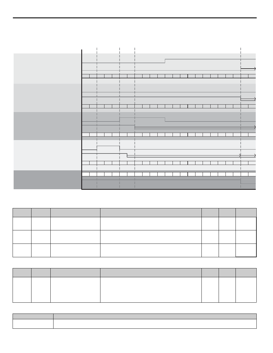
Figure 178. PI Network Feedback Selection
Table 109 Related Parameters
Table 110 Parameters
Table 111 Multi-Function Input Setting
Parameter
No.
Addr.
Hex
Parameter Name
Digital Operator Display
Description
Setting
Range
Factory
Setting
Menu
Location
b5-12
1B0
PI Feedback Reference Missing
Detection Selection
Fb los Det Sel
0: Disabled
1: Alarm
2: Fault
0 ~ 2
2
Programming
b5-13
1B1
PI Feedback Loss Detection
Level
Fb los Det Lvl
Sets the PI feedback lost detection level as a percentage of maximum
frequency (E1-04).
0 ~ 100
0%
Programming
b5-14
1B2
PI Feedback Loss Detection
Time
Fb los Det Time
Sets the PI feedback loss detection delay time in terms of seconds.
0.0 ~
25.5 s
2.0 s
Programming
Parameter
No.
Addr.
Hex
Parameter Name
Digital Operator Display
Description
Setting
Range
Factory
Setting
Menu
Location
P9-02
088
Feedback Source
Feedback Source
Defines which signal to use for PI Feedback when P1-01 = 3.
0: Analog Only
1: Ana => Net, No Alrm
2: Ana => Net, Alarm
3: Network Only
Setting has no effect when P1-01
≠
3.
0 ~ 3
0
Programming
Setting
Description
75
Reset Accum
Closed: Volume accumulated will be reset to zero (and held at zero if digital input remains closed).
Lead Drive
Drive Feedback Good
Lead Drive
Drive Feedback Good
Lead Drive
Drive Feedback Good
Drive 1
Drive 2
Drive 3
Effective PI Feedback
Effective PI Feedback
Lead Drive
Drive Feedback Good
Drive 4
Effective PI Feedback
Effective PI Feedback
Pump Feedback Input from Network
Network Feedback Good
1
1
1
1
1
1
1
1
3
2
2
2
2
2
2
2
2
2
3
3
3
3
3
3
3
3
3
3
3
-
3
3
-
1
3
1
2
3
3
3
3
3
3
3
3
3
3
3
3
3
1
-
-
-
-
-
-
-
-
-
-
-
-
-
-
-
-
1
1
1
1
3
2
2
3
3
3
3
3
3
3
3
3
3
3
-
3
3
-
1
3
3
3
3
3
3
3
3
3
3
3
3
3
3
3
3
3
-
3
3
-
3
3
Network
Feedback is
from Drive 1
(lead)
Network
Feedback is
from Drive 2
because it
became Lead
Network
Feedback
is from
Drive 1
(no lead,
good
signal)
Network Feedback is from Drive 3 because 2 lost its signal
Drive 3
lost its
signal…
no other
FB source
on the
network
P9-02 = 3
(Network Only)
P9-02 = 1
(Ana->Net, No Alrm)
P9-02 = 0
(Analog Only)
P9 -02 = 1
(Ana->Net, Alarm)
B5-12 = 1 or 2
H3-09 = B
B5-12 Action
B5-12
Action
Netwrk
FB Lost
Message
B5-12
Action
Analog FB Lost Alarm