AMETEK BPS Series Programming Manual User Manual
Page 25
BPS / MX / RS Series SCPI Programming Manual
AMETEK Programmable Power
Manual P/N 7003-961 Rev. AA
25
3.3.2
Serial Cable Diagram
For MX/RS/BPS units with an RS232 interface but no USB interface, the following wiring
diagram is required for the serial interface cable between the AC/DC power source and a
PC communications port connector.
DB-9 PC
DB-9 AC Source
Pin
1
2
3
4
5
6
7
8
9
Pin
1
2
3
4
5
6
7
8
9
Direction
output
input
output
output
-
input
-
-
output
Description
reserved
Receive data(RxD)
Transmit data (TxD)
Data Terminal Ready (DTR)
Signal Ground
Data Set Ready (DSR)
no connect
no connect
reserved
Figure 3-1: RS232C Interface cable wiring diagram
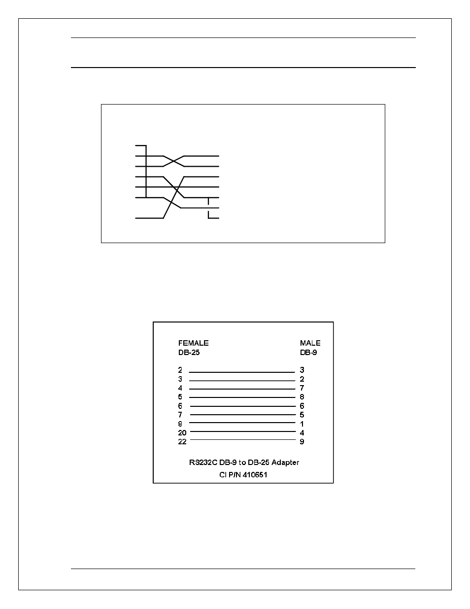
If the controller or PC only has a 25 pin D sub COM port, a 25 to 9 pin adaptor is required to
use the serial cable supplied with the MX/RS/BPS. These small triangular shape adaptors
can be purchased at most computer stores or outlets like Radio Shack. If none can be
found, one can be constructed using the diagram shown below.
Figure 3-2: DB25 to DB9 Adaptor pinout