Labconco PURICARE Procedure Station Models 34812xx User Manual
Page 94
Page 94 of 197
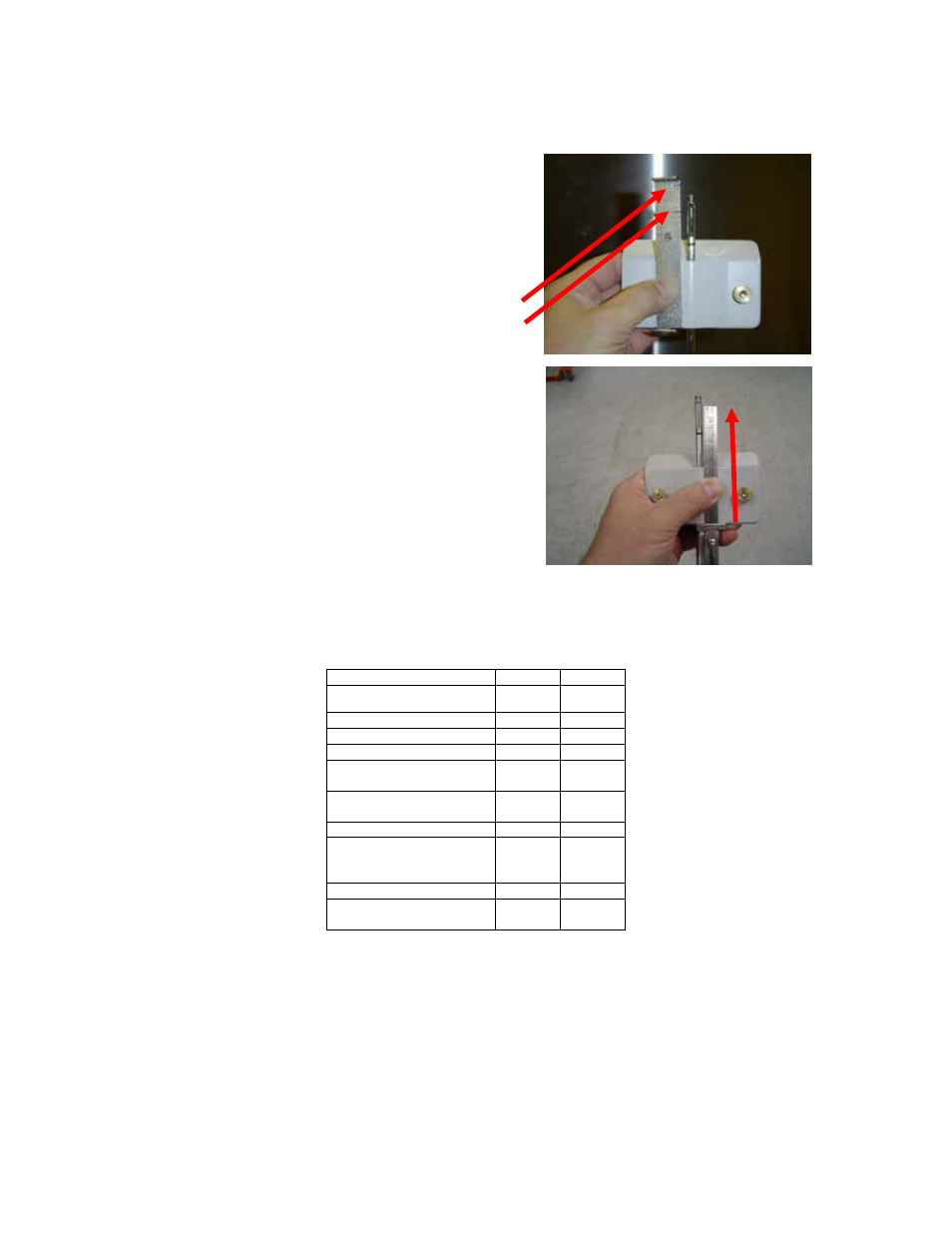
Figure 6-10a & b
The Sensor Distance, as described in Table 6-5,
using the slots cut in the 6-foot template.
4.00-inch
mark
3.25-inch
mark
The Sensor Distance, as described in Table 6-5,
using a scale.
Table 6-5
Secondary Inflow Test Specifications
Model 34410
34610
Restricted Sash Opening
(inches)
2
3 4.25
Sensor distance (inches)
3
4 4
# of Test points
8
12
Test point location
*
*
Nominal Avg. Inflow Vel.
(FPM)
283 231
Avg. Inflow Vel. Range
(FPM)
269-296 220-242
Correction Factor (CF)
1
2
Average Inflow Volume
Range (AIV) (Avg. velocity
x CF)
269-296 403-443
Sash Open Area (Sq. Ft)
2.69
4.03
Inflow Velocity Range
(AIV / Sash open area)
100-110 100-110
1. Locate the single row of holes at the front of the grille. Mark the 6
th
hole from
the side wall and subsequent test points every 9 holes until the number of
test points marked equals the width of the cabinet in feet (for a 4-foot
cabinet, for example, mark the first 4 points). Repeat for the opposite side,
as shown in Figure 6-11.
2. Start the Purifier, and let it operate for at least 5 minutes. Establish the
necessary correction factor to the thermal anemometer to ensure compliance
- PURICARE Procedure Station Models 34810xx PURICARE Procedure Station Models 34802xx PURICARE Procedure Station Models 34800xx Type B2 Biosafety Cabinets Models 34610xx Type B2 Biosafety Cabinets Models 34410xx Type A2 Biosafety Cabinets Models 34609 Type A2 Biosafety Cabinets Models 34509 Type A2 Biosafety Cabinets Models 34409 Type A2 Biosafety Cabinets Models 34309 Type A2 Biosafety Cabinets Models 34608xx Type A2 Biosafety Cabinets Models 34508xx Type A2 Biosafety Cabinets Models 34408xx Type A2 Biosafety Cabinets Models 34308xx Type A2 Biosafety Cabinets Models 34600xx Type A2 Biosafety Cabinets Models 34500xx Type A2 Biosafety Cabinets Models 34400xx Type A2 Biosafety Cabinets Models 34300xx