Adding the optional rs-232 to the logic – Labconco PURICARE Procedure Station Models 34812xx User Manual
Page 184
Page 184 of 197
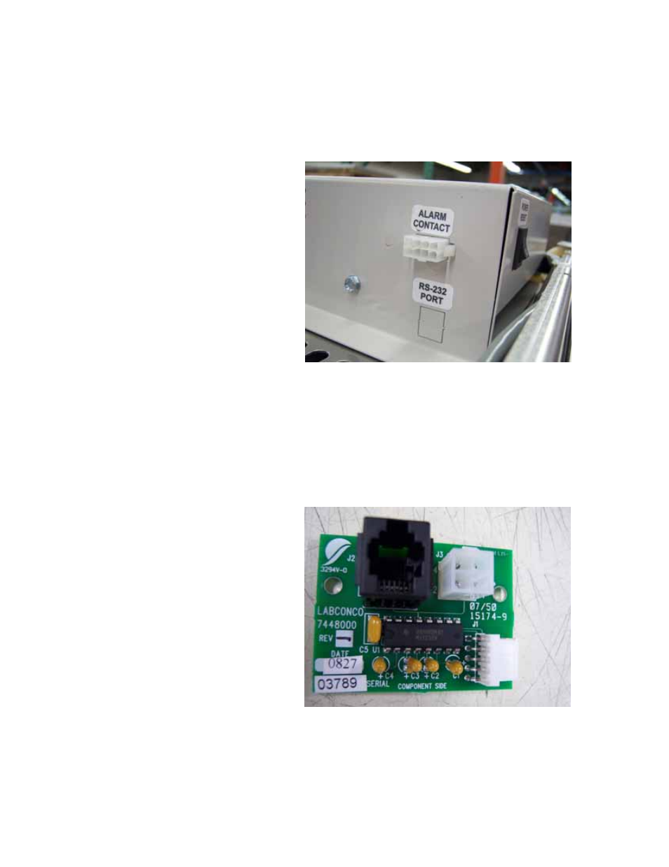
Adding the Optional RS-232 to the Logic
The kit contains the RS-232 PCB (#74480), and the attaching hardware to install the
PCB inside the electrical control box (located on top of the Logic). Picture #1 shows the
general location where the Logic RS-232 PCB will be installed.
WARNING!! DISCONNECT ALL ELECTRICAL POWER FROM THE UNIT BEFORE
BEGINNING THIS PROCEDURE!!!!
To install:
1) Carefully remove the square “knock-out” shown in picture #1 under the “RS-232
Port” label.
2) Locate the black square connecter labeled as J2 on the RS-232 PCB, see picture
#2. Also note the location of the J1 connector for later use.
3) Install the RS-232 PCB inside the electrical control assembly as shown in picture
#3, being careful to locate the J2 connector (found in step 2) thru the square
hole created in step 1. Use the included bolts.
- PURICARE Procedure Station Models 34810xx PURICARE Procedure Station Models 34802xx PURICARE Procedure Station Models 34800xx Type B2 Biosafety Cabinets Models 34610xx Type B2 Biosafety Cabinets Models 34410xx Type A2 Biosafety Cabinets Models 34609 Type A2 Biosafety Cabinets Models 34509 Type A2 Biosafety Cabinets Models 34409 Type A2 Biosafety Cabinets Models 34309 Type A2 Biosafety Cabinets Models 34608xx Type A2 Biosafety Cabinets Models 34508xx Type A2 Biosafety Cabinets Models 34408xx Type A2 Biosafety Cabinets Models 34308xx Type A2 Biosafety Cabinets Models 34600xx Type A2 Biosafety Cabinets Models 34500xx Type A2 Biosafety Cabinets Models 34400xx Type A2 Biosafety Cabinets Models 34300xx