Motor output signal testing – Labconco PURICARE Procedure Station Models 34812xx User Manual
Page 151
Page 151 of 197
Motor Output Signal Testing
Using the Microprocessor “Calibration” Mode to access the “Motor Speed Factor” LCD screen.
Access the “Calibration” Mode by pressing “Menu” and “OK”, then select “Cabinet Set-up” and
“OK” and finally select “Calibration.” Then enter the password sequence “Light, UV, Timer,
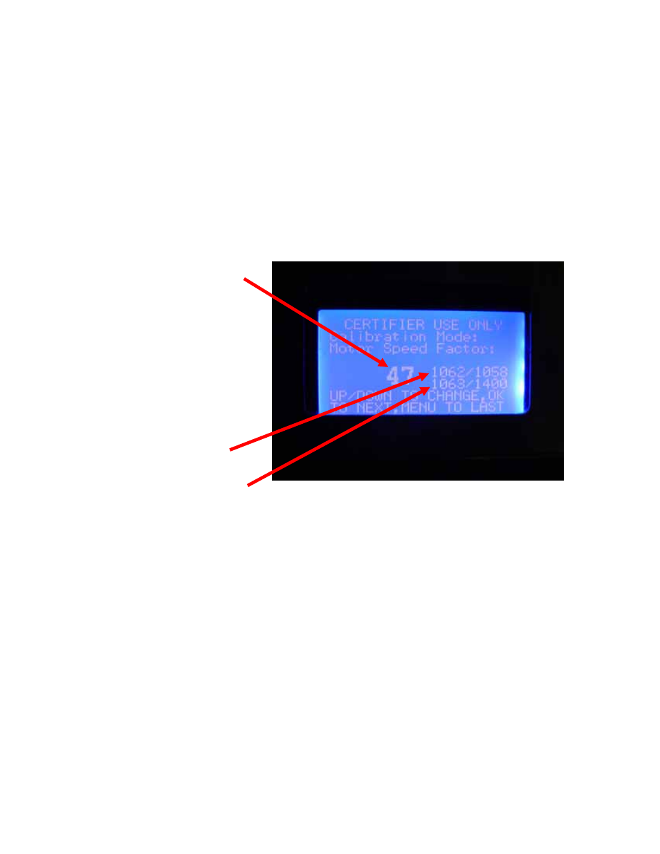
Timer” and then press “OK.” The LCD screen will now show the PWM output % signal and
next to that, the instantaneous and averaged motor RPM signals sent back from the motor to
the electronic controls. Figure 9-13 shows the LCD screen and the location of the RPM
signals. Verify these displayed RPM’s correspond approximately with the actual motor RPM’s.
Figure 9-13
Motor Speed Factor Setting
Motor Speed in RPMs/
Average Motor Speed in RPMs
Motor Speed when new/Maximum motor speed
- PURICARE Procedure Station Models 34810xx PURICARE Procedure Station Models 34802xx PURICARE Procedure Station Models 34800xx Type B2 Biosafety Cabinets Models 34610xx Type B2 Biosafety Cabinets Models 34410xx Type A2 Biosafety Cabinets Models 34609 Type A2 Biosafety Cabinets Models 34509 Type A2 Biosafety Cabinets Models 34409 Type A2 Biosafety Cabinets Models 34309 Type A2 Biosafety Cabinets Models 34608xx Type A2 Biosafety Cabinets Models 34508xx Type A2 Biosafety Cabinets Models 34408xx Type A2 Biosafety Cabinets Models 34308xx Type A2 Biosafety Cabinets Models 34600xx Type A2 Biosafety Cabinets Models 34500xx Type A2 Biosafety Cabinets Models 34400xx Type A2 Biosafety Cabinets Models 34300xx