Labconco PURICARE Procedure Station Models 34812xx User Manual
Page 166
Page 166 of 197
7. Install the new control board by reversing the above steps. Before closing and
securing the side panel, ensure the control circuit board display is centered on
the display window on the cabinet’s side wall. If the display is not centered,
loosen both mounting nuts, and move the control circuit board and its metal
frame until it is centered, then retighten the nuts.
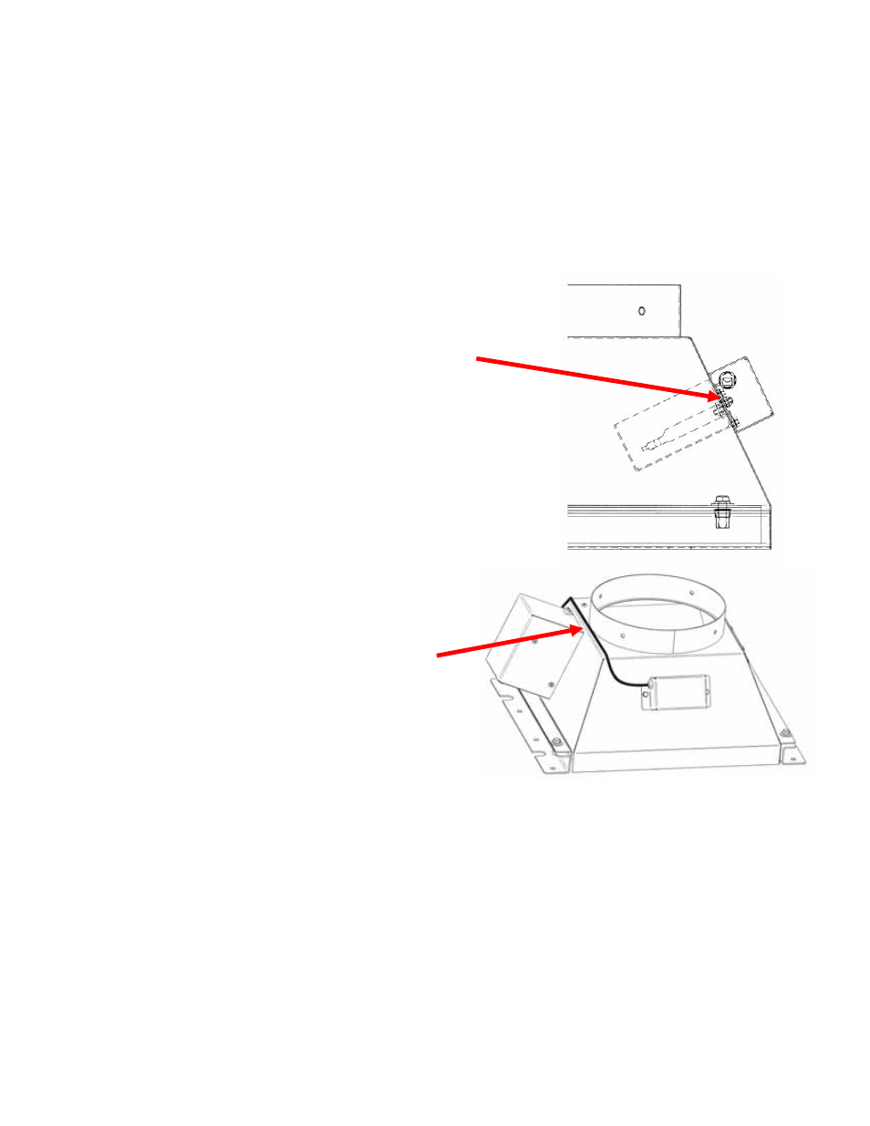
8. Install the sensor assembly into the rear of the canopy connection as shown. Use
the supplied lockwashers and acorn nuts to secure the sensor assembly to the
canopy.
Canopy Air Sensor installation, Side View
Secure the sensor assembly with two lockwashers
and acorn nuts.
NOTE the orientation of the sensor assembly in the
canopy
Canopy Air Sensor installation, Side View
On 6-Foot Cabinets ONLY, ensure the
Sensor cable is secured to the top canopy, using
the wiring harness loops and screws provided.
NOTE: On 6-foot units, ensure the sensor cable
routing does not block or obstruct the operation
of the canopy relief valve on this side of the
canopy.
- PURICARE Procedure Station Models 34810xx PURICARE Procedure Station Models 34802xx PURICARE Procedure Station Models 34800xx Type B2 Biosafety Cabinets Models 34610xx Type B2 Biosafety Cabinets Models 34410xx Type A2 Biosafety Cabinets Models 34609 Type A2 Biosafety Cabinets Models 34509 Type A2 Biosafety Cabinets Models 34409 Type A2 Biosafety Cabinets Models 34309 Type A2 Biosafety Cabinets Models 34608xx Type A2 Biosafety Cabinets Models 34508xx Type A2 Biosafety Cabinets Models 34408xx Type A2 Biosafety Cabinets Models 34308xx Type A2 Biosafety Cabinets Models 34600xx Type A2 Biosafety Cabinets Models 34500xx Type A2 Biosafety Cabinets Models 34400xx Type A2 Biosafety Cabinets Models 34300xx