Labconco PURICARE Procedure Station Models 34812xx User Manual
Page 168
Page 168 of 197
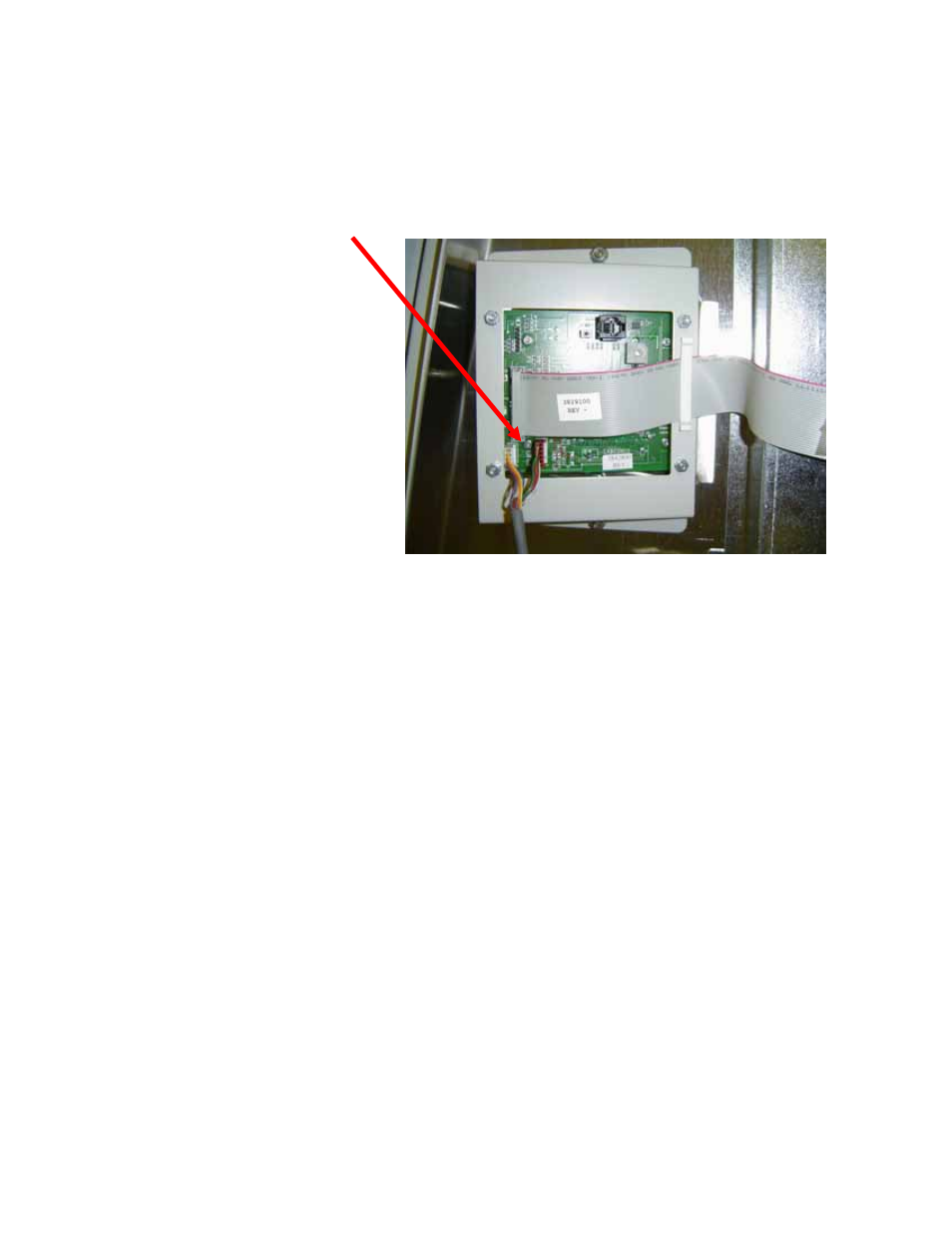
12. Route the cable to avoid pinch hazards, and to bring the two airflow sensor
connectors to the control board. Insert the two connectors into the control
board. One harness connector has 5 pins, and the other has 6. Connect each to
the corresponding pin connectors on the board as shown in the following photo.
Airflow Sensor connectors
13. Reinstall the side panel and reconnect the Logic to electrical service. The unit is
now ready for the calibration of the air flow sensor, once the exhaust system is
started and operating stabily.
Note: You will need to access the certifiers menu to calibrate the airflow
sensor.
Note: To properly calibrate the air flow sensor, a qualified certifier must
verify the inflow and downflow values.
With the Logic operating, press:
“Menu”
The Display will change to Menu mode. Press the up or down arrows ( ^ or v ) until
“Cabinet Setup” is selected. Press:
“Mute/OK”
The Display will then change to the password mode. The password is a sequence of
keys, press:
“Light”
“UV Light”
“Timer”
“Timer”
“Mute/OK”
The display will now change into the speed setting mode.
- PURICARE Procedure Station Models 34810xx PURICARE Procedure Station Models 34802xx PURICARE Procedure Station Models 34800xx Type B2 Biosafety Cabinets Models 34610xx Type B2 Biosafety Cabinets Models 34410xx Type A2 Biosafety Cabinets Models 34609 Type A2 Biosafety Cabinets Models 34509 Type A2 Biosafety Cabinets Models 34409 Type A2 Biosafety Cabinets Models 34309 Type A2 Biosafety Cabinets Models 34608xx Type A2 Biosafety Cabinets Models 34508xx Type A2 Biosafety Cabinets Models 34408xx Type A2 Biosafety Cabinets Models 34308xx Type A2 Biosafety Cabinets Models 34600xx Type A2 Biosafety Cabinets Models 34500xx Type A2 Biosafety Cabinets Models 34400xx Type A2 Biosafety Cabinets Models 34300xx