Introducing the test setup – EXFO FTB-8100 Series Transport Blazer for FTB-200 User Manual
Page 66
Creating and Starting a Test Case
54
FTB-8100 Series Transport Blazer
Introducing the Test Setup
Introducing the Test Setup
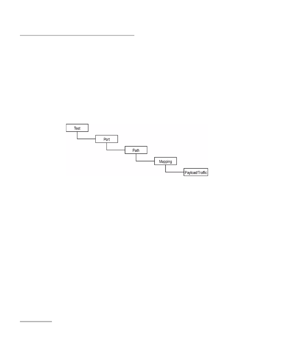
The Test Setup window allows the creation of the test case by navigating
through the signal structure. In the case where the GUI is not in the setup
window, select the Test Setup button from the Global Test Status and
Controls (refer to 31).
The test path is created through the configuration of each layer that must
be crossed by the signal under test. The test path contains the following
nodes:
³
The Test node is the root of the test case. It allows the configuration of
the clock mode and test mode.
³
The Port node allows the selection and configuration of the signal.
³
The Path node allows the selection and configuration of the HOP and
LOP path of a SONET/SDH signal.
³
The Mapping node allows the selection and configuration of the
mapping of the selected signal.
³
The Payload/Traffic node completes the test path by selecting the
pattern.
Note: For decoupled test mode, both TX and RX test nodes (Port, Path, Mapping,
and Payload/Traffic nodes) have to be selected and configured
independently.