4 alarm table – EVCO EPU2LXP1CH Installer manual User Manual
Page 93
EVCO S.p.A.
c-pro 3 micro CHIL | Application manual ver. 1.0 | Codice 144CP3CHE104
page 93 of 120
10.4
Alarm Table
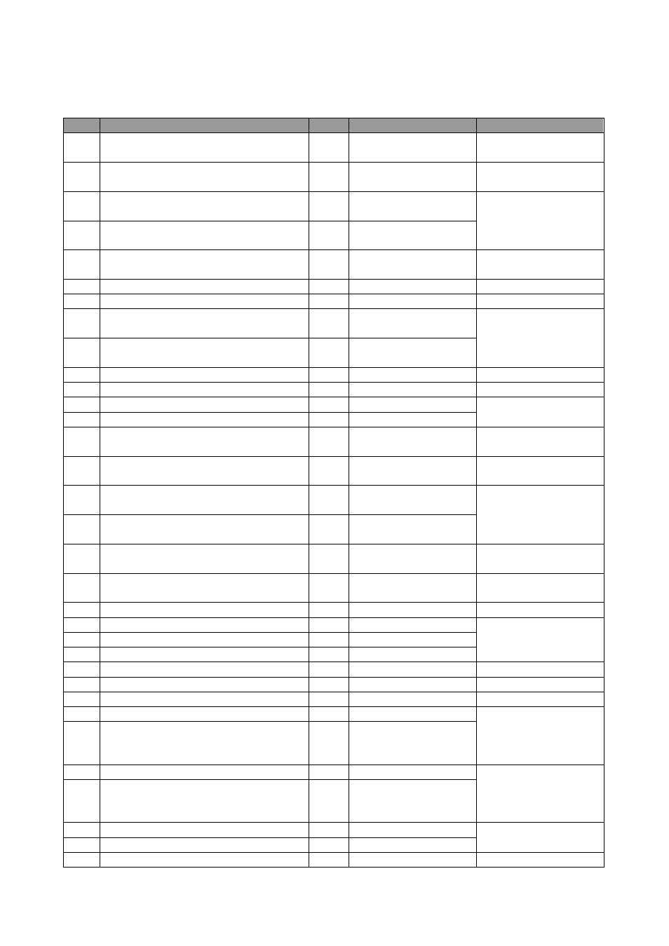
All alarms managed by the application are listed below. The listing order is the same as the one in which alarms are listed when active.
Code
Alarm description
Type
Consequence
Notes
AL01
Input low temperature
S/A
Notification only or
compressors and pump OFF
Heat pump only
Settable delay
AL02
Input high temperature
S/A
Notification only or
compressors and pump OFF
Chiller only
Settable delay
AL03
Primary exchanger efficiency Circuit #1
Manu
Keeps all circuit compressors
OFF
Settable delay
AL13
Primary exchanger efficiency Circuit #2
Manu
Keeps all circuit compressors
OFF
AL05
Evaporator flow meter
A/M
Compressors OFF
Pump ON for T-secs.
Settable delay
In manual stop, pump OFF
AL11
High-pressure pressure switch Circuit #1
Manu
All circuit compressors OFF
AL12
High-pressure pressure switch Circuit #2
Manu
All circuit compressors OFF
AL21
Low-pressure pressure switch Circuit #1
A/M
All circuit compressors and
fans OFF
Settable start-up delay and
rpm
AL22
Low-pressure pressure switch Circuit #2
A/M
All circuit compressors and
fans OFF
AL31
Transducer high pressure Circuit #1
Manu
All circuit compressors OFF
AL32
Transducer high pressure Circuit #2
Manu
All circuit compressors OFF
AL41
Transducer low pressure Circuit #1
A/M
All circuit compressors OFF
Settable start-up delay and
rpm
AL42
Transducer low pressure Circuit #2
A/M
All circuit compressors OFF
AL51
Failed start-up for low pressure Circuit #1
Auto
Keeps all circuit compressors
OFF
AL52
Failed start-up for low pressure Circuit #2
Auto
Keeps all circuit compressors
OFF
AL61
High temperature discharge gas compressors
Circuit #1
A/M
All circuit compressors OFF
Settable delay
AL62
High temperature discharge gas compressors
Circuit #2
A/M
All circuit compressors OFF
AL81
Evaporator anti-frost Circuit #1
Manu
Circuit compressors OFF and
Pump ON for T-secs.
AL82
Evaporator anti-frost Circuit #2
Manu
Circuit compressors OFF and
Pump ON for T-secs.
AF20
Thermal switch external fan free-cooling
A/M
Fan FC OFF
Settable delay
AC21
Thermal switch compressor #1
A/M
Compressor # 1 OFF
Settable delay
AC22
Thermal switch compressor #2
A/M
Compressor # 2 OFF
AC23
Thermal switch compressor #3
A/M
Compressor # 3 OFF
AC24
Thermal switch compressor #4
A/M
Compressor # 4 OFF
AC25
Thermal switch compressor #5
A/M
Compressor # 5 OFF
AC26
Thermal switch compressor #6
A/M
Compressor # 6 OFF
AP21
Thermal switch pump #1
A/M
Pump # 1 OFF
If it is the only pump, turn
off all compressors and fans;
otherwise try to turn on the
other pump.
AP22
Thermal switch pump #2
A/M
Pump # 2 OFF
AP23
Thermal switch source pump #1
A/M
Source Pump # 1 OFF
If it is the only pump, turn
off all compressors and fans;
otherwise try to turn on the
other pump.
AP24
Thermal switch source pump #2
A/M
Source Pump # 2 OFF
AF21
Thermal switch fan Circuit #1
A/M
Fan # 1 OFF
Settable delay
AF22
Thermal switch fan Circuit #2
A/M
Fan # 2 OFF
AC01
Operating hours compressor #1
Auto
Display only