EVCO EPU2LXP1CH Installer manual User Manual
Page 71
EVCO S.p.A.
c-pro 3 micro CHIL | Application manual ver. 1.0 | Codice 144CP3CHE104
page 71 of 120
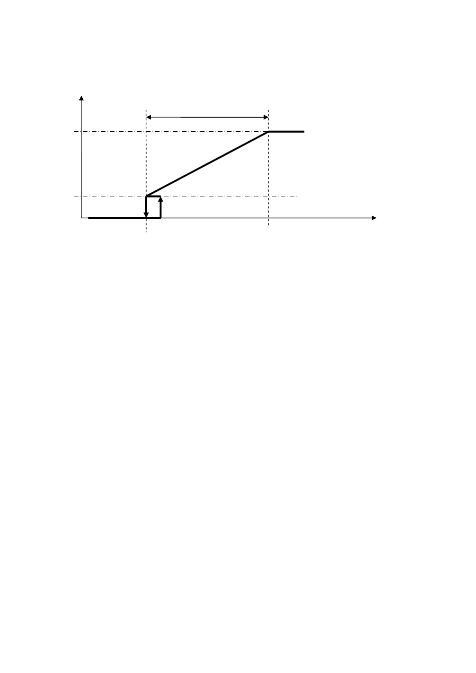
When the temperature reaches the FC Set Point and remains below for more than PS10 seconds, it deactivates free-cooling; the step
shown in the diagram, hysteresis PS08(default 0.5°C), re-enables free-cooling andthe ramp (if ON status is maintained for more than
PS10 seconds).
When free-cooling adjustment is on the steps, the call of the compressor steps is prevented; when the temperature reaches the upper
limit of the proportional band and remains in this state for at leastPS10 seconds, it enables the compressor steps to be called to carry
out the primary adjustment.
The fan can also be the ON/OFF type.
Depending on the configuration of parametersPG13 andPG11, it is possible for free-cooling to act in different ways:
PG13=0: SINGLE AIR CIRCUIT
In the case of single condensation (PG11=1), with active free-cooling the condenser fan will be controlled by the above-
mentioned adjustment according to the entering temperature. If the compressors are turned on as a result of an increase in
power, the controls will be switched from fan control to condenser control and will remain so until there is at least one active
compressor in the circuit in question.
In this configuration, a single fan is used and is the one thatrefers to circuit 1. This fan will handle condensation and free-
cooling (any free-cooling coils must be put in this position).
In the case of separate condensation (PG11=0), a circuit normally regulates condensation, while the other condenser
fan is controlled with the above-mentioned free-cooling adjustment.
In this configuration, the fan used exclusively for condensation is the circuit 2 fan. The circuit 1 fan will handle the
condensation of the appropriate circuit and free-cooling if conditions are there (any free-cooling coils must be put in this
position).
PG13=1: SEPARATE AIR CIRCUIT
In the case of single condensation (PG11=1), orin the case of separate condensation (PG11=0)having two independent
air circuits, there is no need to make a distinction; behaviour is identical. In this situation, it makes sense to use parameter PS05
(enabling of free-cooling with compressors):
•
PS05 = 0. If at least one compressor is on, free-cooling is disabled, otherwise follow normal adjustment of the ramp.
•
PS05 = 1. If at least one compressor is on, the free-cooling ramp is forced to the maximum value (100% or another value set
in parameter PS04), otherwise follow normal adjustment of the ramp.
The condenser fans are independent from free-cooling.
To activate the fan associated with free-cooling, it is necessary to set the associated analog output as well.
T. Regulation
Fan Speed
Set Point FC
Set Point BL
PS02
PS04
PS03
PS08