EVCO EPU2LXP1CH Installer manual User Manual
Page 15
EVCO S.p.A.
c-pro 3 micro CHIL | Application manual ver. 1.0 | Codice 144CP3CHE104
page 15 of 120
6.3
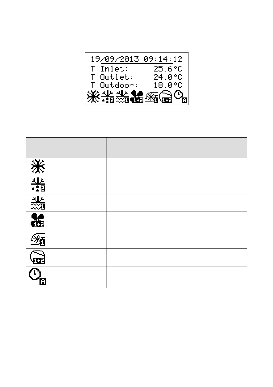
Unit ON main page
When the unit is turned on, the following main screen will be displayed:
At the bottom of the page, icons will be displayed that indicate various statuses of circuit operation.
The table below contains graphic representations of the individual icons, the relative operational status and what is being verified.
From left to right:
Icon
Operational status
Eventdisplayed
Summer/Winter/Alarm Icon
In case there is an active alarm, the alarm icon will be displayed alternatively with
the icon of the operational mode (summer/winter)
Defrost Icon
Indicates that circuit defrost is in progress (1,2).
If flashing, it is in dripping phase
Antifreeze Icon
Indicates that the antifreeze resistance mechanism is active (heat sink or source)
in the circuit indicated (1,2 1+2)
Fan Icon
Indicates that the circuit fans (1,2, 1+2) are active
Pump Icon
Indicates which circulation pump (1,2) is active
Compressor Icon
Indicates that at least one circuit compressor (1,2, 1+2) is active
Time Slot Icon
Indicates which time slot is active (A,B)
From this page, by pressing the RIGHT or LEFT keys, it is possible to display other information regarding pumps, fans, compressors,
defrost, circuit status, RTC and all configured sensors. In case of fault status of the sensors, the value field of the corresponding sensor
displays “----“, or else “----“ if the sensor is disabled.
Pressing the ESC key from this page brings the user to the Alarm page.