EVCO EPU2LXP1CH Installer manual User Manual
Page 64
EVCO S.p.A.
c-pro 3 micro CHIL | Application manual ver. 1.0 | Codice 144CP3CHE104
page 64 of 120
8.8.2
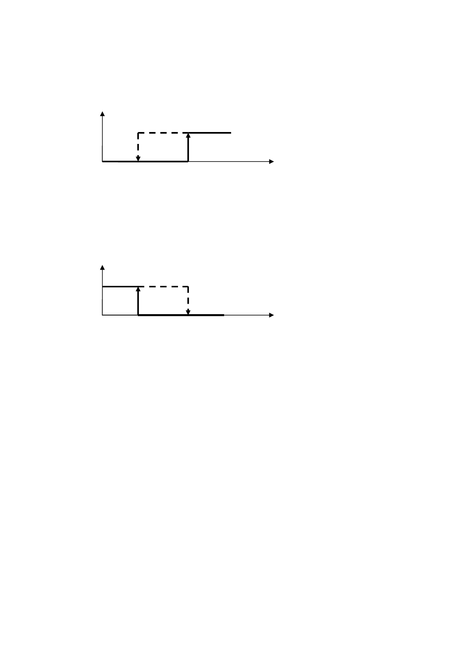
Single stage fan control
Manage a single stage control of condenser fans by a digital output for every fan.
The condenser fan is switched on when the condenser pressure exceeds the condenser setpoint + condenser pressure differential. The
condenser fan is switched off when the condenser pressure falls below the condenser setpoint, see also next picture.
Mode = Operating mode (0 = Summer)
PF11 = Summer condenser control set point (SP)
PF12 = Summer condenser control differential
The condenser fan is switched on when the condenser pressure falls below the condenser setpoint - condenser pressure differential. The
condenser fan is switched off when the condenser pressure exceeds the condenser setpoint.
Mode = Operating mode (1 = Winter)
PF21 = Winter condenser control set point (SP)
PF22 = Winter condenser control differential
8.8.3
Condenser valve control
On water-to-water machines, during summer operation, the water feeding the condensing circuit is controlled according to condensing
pressure, via a valve (this can be a two-way solenoid or motor- operated pressure-switch valve, modulating with a 0-10 V control-
generated signal). Condenser control is performed in similar fashion to fan speed control. The condenser valve control is a proportional
integral control type.
In order to utilize only a proportional control you need to only set the integral time to zero (PF16=0, PF26=0). Setting an integral time
greater than zero will provide a more precise control, the integral part is tasked with bringing the output up to speed reducing the
error introduced by the sole proportional component (by default the integral component is disabled).
8.8.4
Single condenser
On twin-circuit machines, it is possible to choose to use only one circuit to manage condensation. In order to enable this function, it is
necessary to set PG11=1. Condensing is performed by the fan in Circuit # 1, using the highest of the condensing pressure/temperature
values acquired from the respective transducers.
The activated analogue/digital output is always the one related to Circuit # 1.
Press.
Fan
PF11+ PF12
PF11
ON
PF11 = Summer condensation control set
point
PF12 = Summer condensation control
differential
OFF
Press.
PF21
PF21-PF22
ON
PF21 = Winter condensation control
set point
PF22 = Winter condensation control
differential
OFF
Fan