EVCO EPU2LXP1CH Installer manual User Manual
Page 18
EVCO S.p.A.
c-pro 3 micro CHIL | Application manual ver. 1.0 | Codice 144CP3CHE104
page 18 of 120
6.5
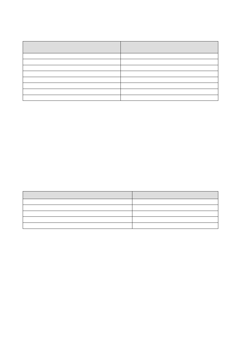
General Menu
The general menu has no level and represents the access point for all the other system menus.
Display LCD
Display LED
USER
USEr
MAINTENANCE
MAin
INSTALLER
InSt
CONSTRUCTOR
CoSt
RTC
rTC
ALARMS
ALrm
HISTORY
HiSt
Not present
StAt
It is possible to view this menu from any point within the user interface by pressing ENTER for approximately 2 seconds. From this
menu you can choose the menu you wish to view by pressing the UP and DOWN keys followed by pressing the ENTER key for
confirmation.
In the upper right hand corner of the image appears a “v” which represents the focus.
This indication specifies to the user that additional information is contained therein and can be viewed by pressing the DOWN key (or
UP key depending on the direction of the focus) scrolling to view the content that is not viewable in the current page.
6.6
User Menu
The User menu is a Level 1 menu, i.e. it requires entering of the User level (or higher) password, in order to be able to display/modify
the parameters contained in this branch.
6.7
Maintenance Menu
The Maintenance menu is a Level 2 menu, i.e. it requires entering of the Maintenance operator level (or higher) password, in order to
be able to display/modify the parameters contained in this branch.
Display LCD
Display LED
OPERATION
OPEr
MANUAL
MAnU
CALIBRATION
CAL
IN/OUT
I-O
PASSWORD
PSd2
In this menu, it is possible to view the status of the various devices, inputs and outputs utilized by the application.
In the OPERATION menu, it is possible to view/enable the features relating to the operation of compressors, fans and pumps. Some
examples of these are the hours of operation, the threshold of maximum allowable hours.
In the MANUAL menu, it is possible to set to manual/automatic operation compressors, pumps and fans, whose outputs can be forced,
in order to test their functionality.
In the CALIBRATION menu, it is possible to set the corrections to be applied to analogue inputs, to compensate the offsets due to
cabling and sensor positioning.
In the I/O STATUS menu, it is possible to view directly the card’s physical inputs and outputs