EVCO EPU2LXP1CH Installer manual User Manual
Page 42
EVCO S.p.A.
c-pro 3 micro CHIL | Application manual ver. 1.0 | Codice 144CP3CHE104
page 42 of 120
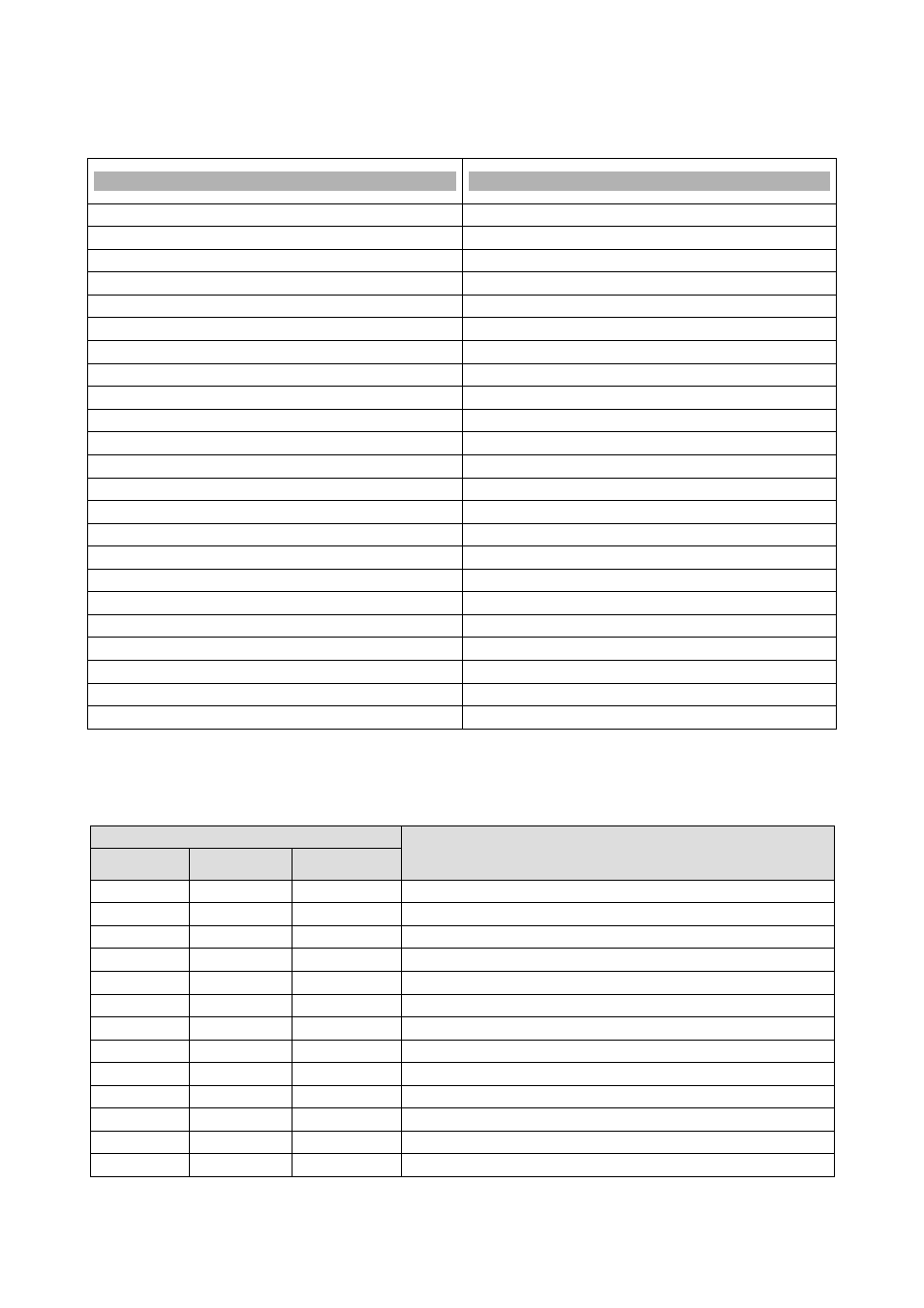
7.3
DI Configuration(HB01-HB18 parameters)
Below is a table of values for configuring the positions of the digital inputs of the controller and of the expansion.
HB01-HB18 Parameters
Digital Inputs
0
Disabled
1-2
Summer/Winter NC-NO
3-4
On/Off NC-NO
5-6
Set point change NC-NO
7-8
Heat sink exchanger flow meter NC-NO
9-10
Heat source exchanger flow meter NC-NO
11-12
Heat sink exchanger Heat pump 1 NC-NO
13-14
Heat sink exchanger Heat pump 2 NC-NO
15-16
Heat source exchanger Heat pump 1 NC-NO
17-18
Heat source exchanger Heat pump 2 NC-NO
19-20
Free Cooling external heater fan NC-NO
21-22
High pressure Circuit 1 NC-NO
23-24
Low pressure Circuit 1 NC-NO
25-26
Thermal compressor 1 NC-NO
27-28
Thermal compressor 2 NC-NO
29-30
Thermal compressor 3 NC-NO
31-32
Circuit1 heater fan NC-NO
33-34
High pressureCircuit 2 NC-NO
35-36
Low pressureCircuit 2 NC-NO
37-38
Thermal compressor 4 NC-NO
39-40
Thermal compressor 5 NC-NO
41-42
Thermal compressor 6 NC-NO
43-44
Circuit 2 heater fanNC-NO
7.4
AO Configuration (HC01-HC18 parameters)
Below is a table of values for configuring the positions of the analog outputs of the controller and of the expansion.
Parameters
Analog Outputs
HC01 HC02
HC07 HC08
HC03 HC04
HC09 HC10
HC05 HC06
HC11 HC12
0
0
0
Disabled
1
1
1
Free Cooling 3-way valve (0-10V)
2
2
2
Free Cooling external fan(0-10V)
3
3
3
Circuit 1 ventilation (0-10V)
4
4
4
Circuit 1 water valve (0-10V)
5
5
5
Circuit 2 ventilation (0-10V)
6
6
6
Circuit 2 water valve (0-10V)
7
-
-
Free Cooling external fan (PWM)
8
-
-
Circuit 1 ventilation(PWM)
9
-
-
Circuit 2 ventilation(PWM)
-
7
-
Free Cooling external fan (4-20mA)
-
8
-
Circuit 1 ventilation (4-20mA)
-
9
-
Circuit 2 ventilation (4-20mA)