EVCO EPU2LXP1CH Installer manual User Manual
Page 45
EVCO S.p.A.
c-pro 3 micro CHIL | Application manual ver. 1.0 | Codice 144CP3CHE104
page 45 of 120
8.2
Unit Type
With the machine in OFF status, using the PGUT parameter from the CONSTRUCTOR/CONFIGURATION menu, it is possible to select
the unit type to be used. Control and other parameters corresponding to the various functions must be manually modified according to
user requirements. All the default unit have 2 compressors for each circuit.
Managed machines are listed below, together with their respective input and output configurations.
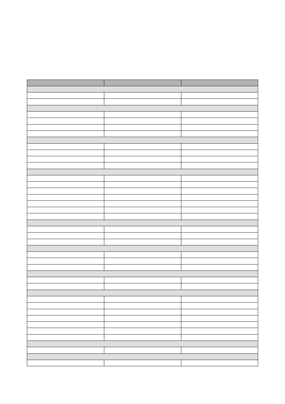
8.2.1
Water-To-Water Chiller with EVDRIVE03
PGUT=1(1 Circuit)
PGUT=9(2 Circuit)
Controller Analog Inputs
A/I 1
Heat sink exchanger input temperature
Heat sink exchanger input temperature
A/I 2
Heat sink exchanger output temperature
Heat sink exchanger output temperature
Analog InputsEVDRIVE03 circuit 1
A/I 1
Condensing pressure C1 (4-20mA)
Condensing pressure C1 (4-20mA)
A/I 2
Compressor discharge temperatureC1
Compressor discharge temperature C1
A/I 3
Compressor intake temperatureC1
Compressor intake temperature C1
A/I 4
Evaporation pressure C1 (4-20mA)
Evaporation pressure C1 (4-20mA)
Analog Inputs EVDRIVE03 circuit 2
A/I 1
Not present
Condensing pressure (4-20mA) C2
A/I 2
Not present
Compressor discharge temperature C2
A/I 3
Not present
Compressor intake temperature C2
A/I 4
Not present
Evaporation pressure (4-20mA) C2
Controller Digital Inputs
D/I 1
On/Off
On/Off
D/I 2
Heat sink exchanger flow meter
Heat sink exchanger flow meter
D/I 3
Heat sink heat pump 1
Heat sink heat pump 1
D/I 4
Thermal compressor 2
Thermal compressor 2
D/I 5
Heat source heat pump 1
Heat source heat pump 1
D/I 6
Heat source exchanger flow meter
Heat source exchanger flow meter
D/I 7
Not used
Thermal compressor 5
Digital InputsEVDRIVE03 circuit 1
D/I 1
High pressure C1
High pressure C1
D/I 2
Low pressure C1
Low pressure C1
D/I 3
Thermal compressor 1
Thermal compressor 1
Digital InputsEVDRIVE03 circuit 2
D/I 1
Not present
High pressure C2
D/I 2
Not present
Low pressure C2
D/I 3
Not present
Thermal compressor4
Controller Analog Outputs
A/O 1
Water valve C1 (0-10V)
Water valve C1 (0-10V)
A/O 2
Not used
Water valve C2 (0-10V)
Controller Digital Outputs
D/O 1
Heat sink pump 1
Heat sink pump 1
D/O 2
Compressor 1
Compressor 1
D/O 3
Compressor 2
Compressor 2
D/O 4
Heat sink anti-frost resistance C1
Heat sink anti-frost resistance C1
D/O 5
Source pump
Source pump
D/O 6
Not used
Compressor 4
D/O 7
Not used
Compressor5
Digital OutputsEVDRIVE03 circuit 1
D/O VCM 1
Solenoid valve C1
Solenoid valve C1
Digital OutputsEVDRIVE03 circuit 2
D/O VCM 2
Not present
Solenoid valve C2