2 installation of the special power supply unit – KEYENCE BL-600 Series User Manual
Page 91
81
Chapter 5 Installation
5
5.2
Installation of the Special Power Supply Unit
This section describes how to install the special power supply units BL-U1, BL-U2,
and N-42.
5.2.1 In-panel installation
To mount the power supply unit BL-U1, BL-U2 or N-42, carefully observe the
following instructions.
•
Provide enough ventilation space.
•
If the ambient temperature may fall below 0
°C or exceed 50°C, provide a fan or
air conditioner.
•
Do not mount this unit in a panel where a high voltage device is installed.
•
Place this unit as far away from power lines as possible.
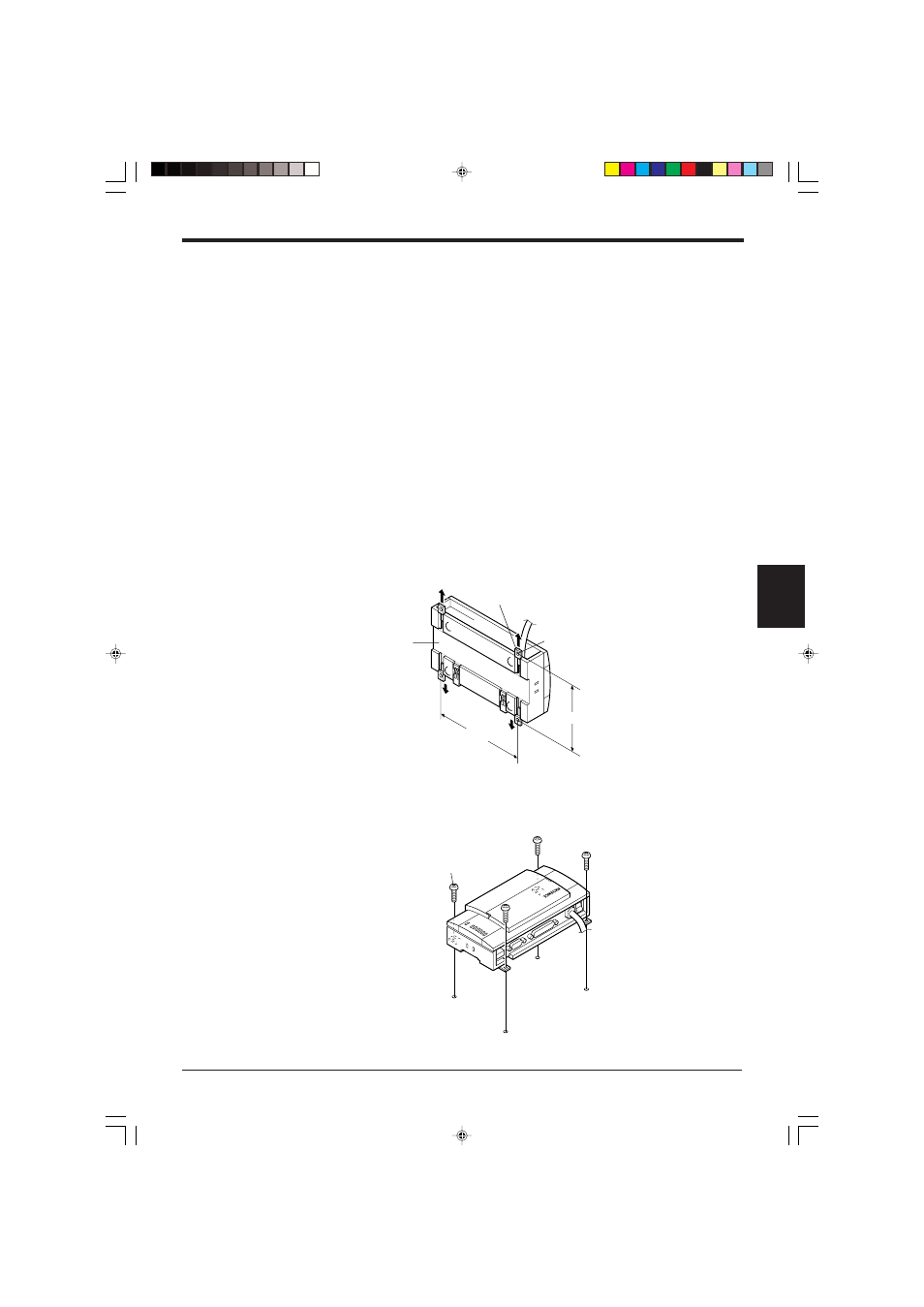
5.2.2 Installing the BL-U1
There are 2 methods for installing the BL-U1.
■ Screw mounting
1. Pull out the 4 screw slot tabs from the rear panel of the BL-U1.
2. Secure the BL-U1 with screws.
*
The mounting screws are not included.
150mm
98mm
Pull out the tab.
Screw hole tab
Mounting hole (4-ø5)
BL-U1
Mounting screw
- LR-TB2000 Series (12 pages)
- LR-TB5000 Series (12 pages)
- LR-ZB250AN/AP (4 pages)
- LR-ZB250AN/P (3 pages)
- LR-ZBxN/P Series (3 pages)
- LR-ZBxxB (3 pages)
- OP-85135 (1 page)
- PZ-G Series (2 pages)
- PZ-V/M (2 pages)
- PS-N10 Series (12 pages)
- PX-10 (10 pages)
- CZ-V21A(P) (10 pages)
- CZ-K1(P) (8 pages)
- CZ-V1 (8 pages)
- FS-N10 Series (6 pages)
- FS-N10 Series (116 pages)
- FS-N15CN (1 page)
- FU-93(Z) (2 pages)
- FU-V Series (2 pages)
- FS-V30 (6 pages)
- FU-A40 (1 page)
- NU/FS-N Series (16 pages)
- FS-V33(P) (8 pages)
- FS-V21 (4 pages)
- FS-V22 (4 pages)
- FS-V11(P) (4 pages)
- FS-V1(P) (4 pages)
- LV-N10 Series (12 pages)
- LV-N10 Series (112 pages)
- LV-S62 (1 page)
- OP-84350 (1 page)
- LV-SA (10 pages)
- LV-SB (12 pages)
- OP-87305 (1 page)
- LV Series (10 pages)
- LV-B102 (1 page)
- EV-108M(U) (1 page)
- EZ Series (1 page)
- EM Series (1 page)
- ES-M1(P) (3 pages)
- EX-V Series (120 pages)
- EX-500(W) Series (16 pages)
- GV Series (10 pages)
- IA Series (8 pages)
- LB-1000(W) (24 pages)