3 detailed description of device assignment – KEYENCE BL-600 Series User Manual
Page 147
137
Chapter 8 PLC Link
8
8.3.3 Detailed description of device assignment
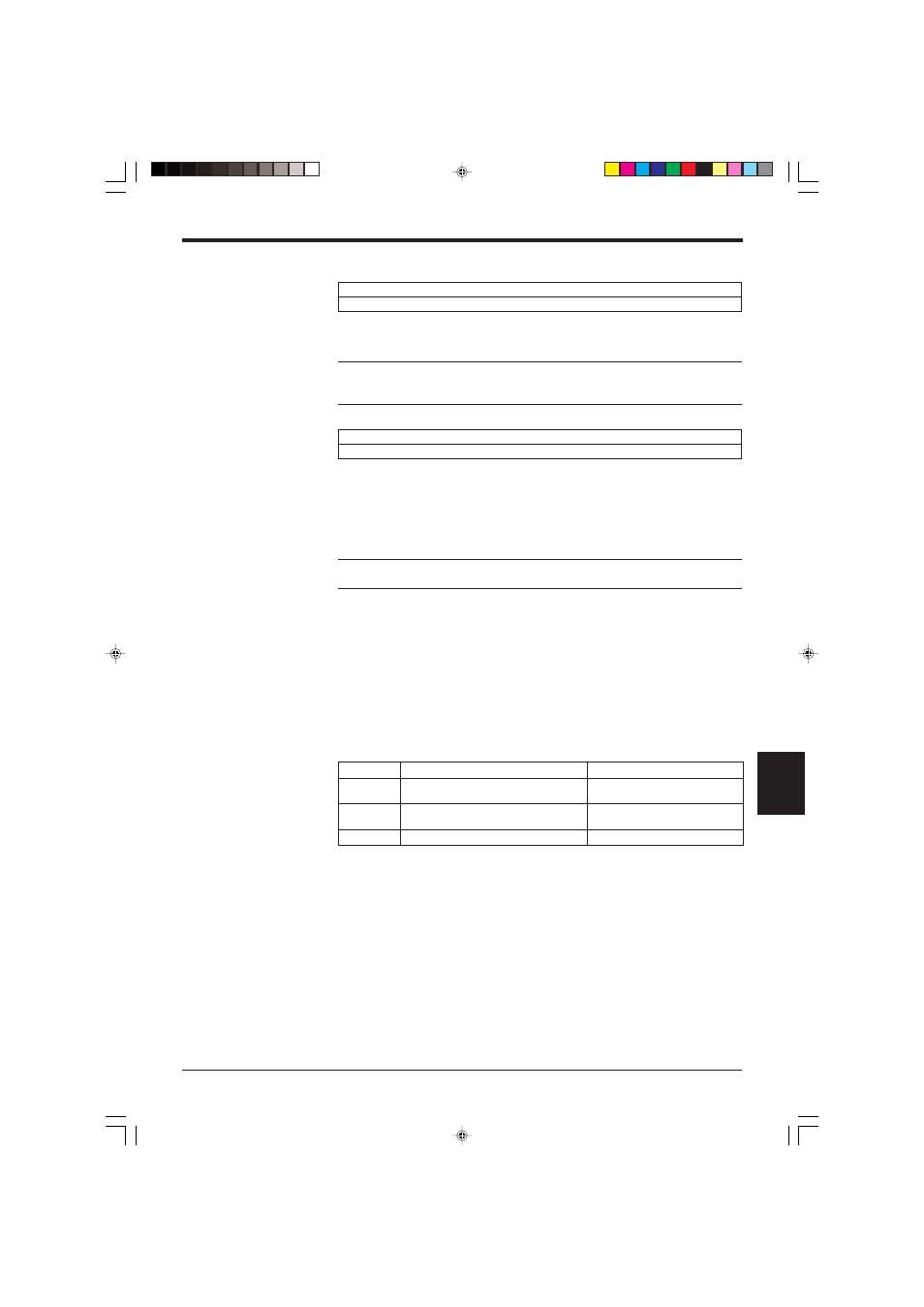
Specify the head address of the areas where the read data is stored.
*
Specify the head address as binary data.
Note: When using the BL-600 in multi-label read mode 3, +00 to +03 are used as
the data memory head address for Codes 1 to 4, respectively. However, data is not
stored in the area for which the code type is not set.
These areas are used to send the trigger input signal to the BL-600 to start reading
bar code data.
*
If the BL-600 Series is set to disable the “PLC Trigger Area”, data is not as-
signed to the data memory head address area. You can use this area for other
purposes.
Note: When connecting a photoelectric sensor for trigger input in the BL-600
Series, do not use these areas.
The method for using the areas varies depending on the BL-600 scan method,
“Level signal trigger” or “One-shot signal trigger”. Each case is described below.
■ When “Level signal trigger” is set
•
“Reading trigger area” at the +04 address is used to trigger the BL-600 to start
reading the data (turn on the laser beams).
•
“Trigger input response area” at the +05 address is used to check whether the
data at +04 was sent correctly to the BL-600. When the BL-600 recognizes the
+04 address (which means that the process has been completed), it returns a
“1” to the +05 address.
+00 to +03
Data memory head address
+04 to +06
Reading trigger area
s
s
e
r
d
d
A
n
o
i
t
p
i
r
c
s
e
D
a
t
a
D
4
0
+
a
e
r
a
r
e
g
g
i
r
t
g
n
i
d
a
e
R
N
O
r
e
g
g
i
r
T
.
.
.
1
F
F
O
r
e
g
g
i
r
T
.
.
.
0
5
0
+
a
e
r
a
e
s
n
o
p
s
e
r
t
u
p
n
i
r
e
g
g
i
r
T
d
e
t
e
l
p
m
o
c
s
s
e
c
o
r
P
.
.
.
1
d
e
t
e
l
p
m
o
c
t
o
n
s
s
e
c
o
r
P
.
.
.
0
6
0
+
d
e
v
r
e
s
e
R
d
e
v
r
e
s
e
R