3 device assignment – KEYENCE BL-600 Series User Manual
Page 145
135
Chapter 8 PLC Link
8
8.3
Device Assignment
The data areas used to control the BL-600 are provided in the PLC’s internal
memory (D areas or DM areas).
When a device head address is specified on the “PLC SETUP” screen in the BL-
600 setup software, the device numbers are automatically assigned based on the
specified head address.
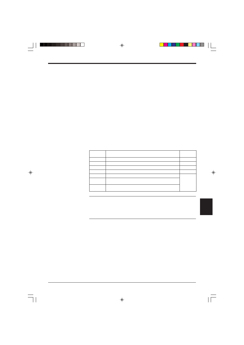
8.3.1 Data memory head address
[Specified head address] +00 indicates the area where the bar code data is stored.
[Specified head address] +01 to +03 are reserved areas and cannot be assigned
for the bar code data.
[Specified head address] +04 to +06 are the areas used by the PLC to send a
reading trigger to the BL-600.
*
The method for using the areas varies depending on the BL-600 scan method,
“Level signal trigger” or “One-shot signal trigger”.
*
If the BL-600 Series is set to disable the “PLC Trigger Area”, data is not as-
signed to the data memory head address area. You can use this area for other
purposes.
Note 1: When using the BL-600 in multi-label read mode 3, addresses +00 to +03
are used as the data memory head addresses for Codes 1 to 4, respectively. Data
is not stored in the areas for which the code type is not set.
Note 2: If using the BL-600 Series in multi-label read mode 1 or 2, the read data is
written one at a time to the area specified with address +00 in the order of the
reading.
s
s
e
r
d
d
A
n
o
i
t
p
i
r
c
s
e
D
e
c
n
e
r
e
f
e
R
e
g
a
p
0
0
+
1
e
d
o
C
r
o
f
s
s
e
r
d
d
a
d
a
e
h
y
r
o
m
e
m
a
t
a
D
7
3
1
1
0
+
2
e
d
o
C
r
o
f
a
e
r
a
d
e
v
r
e
s
e
R
7
3
1
2
0
+
3
e
d
o
C
r
o
f
a
e
r
a
d
e
v
r
e
s
e
R
7
3
1
3
0
+
4
e
d
o
C
r
o
f
a
e
r
a
d
e
v
r
e
s
e
R
7
3
1
4
0
+
a
e
r
a
r
e
g
g
i
r
t
g
n
i
d
a
e
R
9
3
1
o
t
7
3
1
5
0
+
a
e
r
a
e
s
n
o
p
s
e
r
r
e
g
g
i
r
t
g
n
i
d
a
e
R
.
d
e
t
c
e
l
e
s
s
i
”
r
e
g
g
i
r
t
l
a
n
g
i
s
l
e
v
e
L
“
n
e
h
w
y
l
n
O
*
6
0
+
a
e
r
a
p
u
t
e
s
e
m
i
t
r
e
g
g
i
r
t
t
o
h
s
-
e
n
O
.
d
e
t
c
e
l
e
s
s
i
”
r
e
g
g
i
r
t
l
a
n
g
i
s
t
o
h
s
-
e
n
O
“
n
e
h
w
y
l
n
O
*