5 wiring the rs-422a – KEYENCE BL-600 Series User Manual
Page 33
Chapter 3 Connection and Installation
23
3
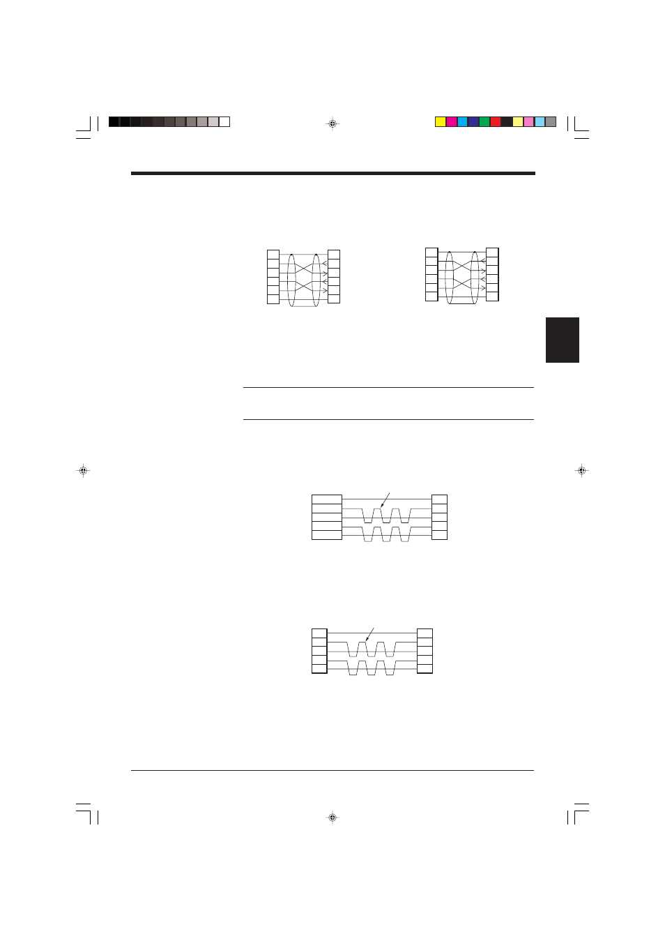
■ SYSMAC-CV Series
Connection with CV500-LK201(Port 1)
Connection with CV500-LK201 (Port 2),
CV500,
CV1000,
CVM1
3.1.5 Wiring the RS-422A
Note 1: The cable can be extended to within 1.2 km.
Note 2: Turn ON the terminators (BL-U1/external unit terminal resistance: 100
Ω).
➮ See page 17.
Connect the BL-U1 to other devices with the following wiring.
■ Connecting a general RS-422A unit
Use the same wiring when connecting the BL-U1 to the BL-U1*.
■ Connecting the MELSEC-A Series
Connecting with AJ71(U)C24(-S
■
■
),
AJ71QC24-R4,
A0J2-C214-S1,
A1SJ71(U)C24-R4
2
Link unit
SD
RD
RS
CS
SG
3
4
5
7
2
1
1
BL-U1*
SD
FG
FG
RD
RS
CS
SG
3
4
5
7
D-sub 25-pin (male)
M2.6 screw
D-sub 25-pin (male)
M2.6 screw
2
PLC
SD
RD
RS
CS
SG
3
4
5
9
2
1
1
BL-U1*
SD
FG
FG
RD
RS
CS
SG
3
4
5
7
D-sub 25-pin (male)
M2.6 screw
D-sub 9-pin (male)
M2.6 screw
* KEYENCE option OP-22149 (1.5 m) or
commercially available cross cable can be
used.
SDA
SG
BL-U1*
SDB
RDA
RDB
RD + (RDA)
SG
External unit
BL-U1*
RD – (RDB)
SD + (SDA)
SD – (SDB)
Twisted pair cable
SDA
SG
BL-U1*
SDB
RDA
RDB
RDA
SG
Link unit
RDB
SDA
SDB
Twisted pair cable