Status bar, Input/output grids, Status bar input/output grids – Aviom Pro64 Network Manager User Manual
Page 74: V w y x
65
P
ro
64 N
etwork
M
aNager
U
ser
g
Uide
Status Bar
Each Device Window contains a read‑only status bar along its bottom edge. A copy of the A‑Net status
icon from the Network Overview will appear in the device window along with Control Master and Clock
Master icons as needed.
v
w
y
x
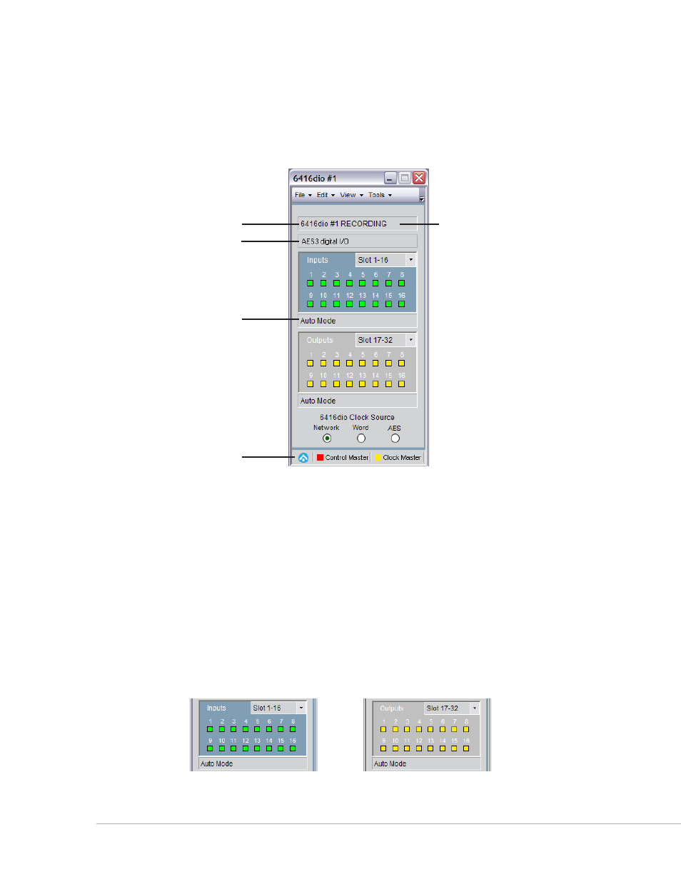
Device type and number (1), Location (2), User Label (3), network mode field (4), and status bar (5)
Input/Output Grids
Pro64 input‑ and output‑capable devices will have I/O grids in their device windows. Bidirectional devices
such as the AllFrame, 6416Y2 A‑Net Interface Card and 6416dio Digital I/O Module will have both types.
Exceptions are noted in the sections that follow.
The grids serve a twofold purpose—they provide a quick overview of channel and Slot use on each Pro64
device and they can be used to quickly activate channels and assign them to network Slots; simply click a
channel to activate/deactivate it.
Inputs are displayed in green, outputs are yellow. The input and output channel grids are numbered 1‑16,
corresponding to the 16 physical connections on the rack‑mount Pro64 I/O devices.
Input grid (left) and output grid (right) with Slot range drop down menus