Figure 18 - cable carrier module replacement, Cable carrier module installation – Rockwell Automation CHPS-250 Linear Stage Installation User Manual
Page 64
64
Rockwell Automation Publication CHPS-UM001D-EN-P - July 2014
Chapter 10
Removing and Replacing Stage Components
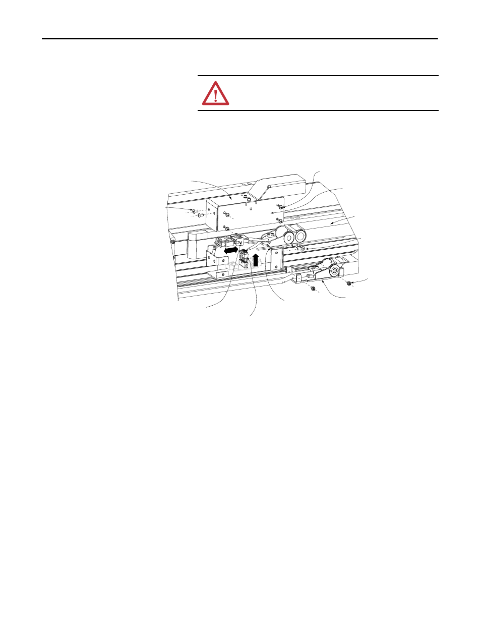
3. Remove junction box cover assembly.
4. Separate motor power connector by squeezing the side tabs and pulling on
the housing. Do not pull on the wires
Figure 18 - Cable Carrier Module Replacement
5. Separate the feedback connector from the circuit board by pushing on the
center tab and pulling up on the connector housing. Do not pull on wires.
6. Remove the two (2) SHCS from the angle bracket.
7. Lay the cable carrier out flat and mark the location of the end bracket on
the base.
8. Loosen but do not remove the two (2) SHCS that secure the end bracket
to the stage base.
9. Remove cable carrier.
Cable Carrier Module
Installation
Align the cable carrier module with the marks made before removing and follow
cable carrier removal procedure in reverse.
ATTENTION: Never pull on wires when disconnecting power and
feedback connectors. Damage to the connector can occur.
Junction Box Side Cover
Junction Box Cover
Cable Carrier Module
Angle Bracket
End Bracket
Feedback Connector
Motor Power Connector
M3 0.5 X8 LG Phillips Pan Head Screws (4x)
M4 X 0.7 X 8 LG BHCS (2x)
M4 X 0.7 X 10 LG SHCS (2x)
M3 X 0.5 X 8 LG SHCS (2x)