Figure 16 - hall signals waveforms – Rockwell Automation CHPS-250 Linear Stage Installation User Manual
Page 56
56
Rockwell Automation Publication CHPS-UM001D-EN-P - July 2014
Chapter 8
Troubleshooting
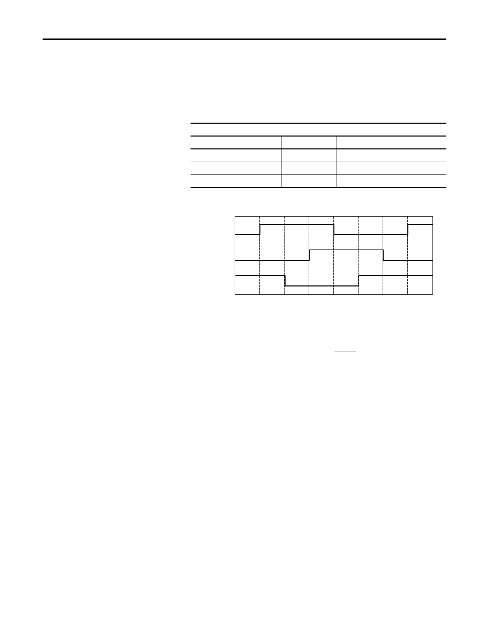
Move the slide slowly and steadily by hand in the specified phasing
direction to generate the Hall waveform.
5. Check for proper logic levels (approximately 0V = low, V+= high) and
correct signal sequence (S1 leads S2, and S2 leads S3) with approximately
120° electrical spacing between signal transitions.
Figure 16 - Hall Signals Waveforms
6. Before assuming a Hall module fault check Hall field wiring or drive Hall
circuit interface.
Hall Effect Leads
Color
Name
Signal Description
White/Green
S1
Trapezoidal Hall, TTL-Single
Blue
S2
Trapezoidal Hall, TTL-Single
White/Blue
S3
Trapezoidal Hall, TTL-Single
TIP
Connect the common probe from the scope to the Hall signal common.
To determine the location of the signal common, refer to the Stage Power and
Feedback Connections beginning on
0°
60°
120°
180°
240°
300°
360°
S1
S2
S3