Rockwell Automation CHPS-250 Linear Stage Installation User Manual
Page 19
Rockwell Automation Publication CHPS-UM001D-EN-P - July 2014
19
Understanding Your Stage
Chapter 2
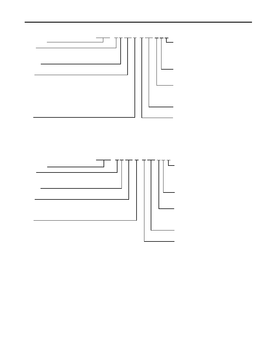
Bulletin Number
Voltage
A= 230V AC
B= 460V AC (LC motors only)
Frame Size
8= 200 mm base
Stroke
For -100 and -120 motor coil lengths
Travel lengths start at 6 cm and are available in 6 cm increments.
For example: 006 for 6 cm travel or 054 for 54 cm travel.
Maximum travel = 126 cm.
Travel lengths start at 8 cm and are available in 6 cm increments.
For -200 or -240 motor coil lengths.
For example: 008 for 8 cm travel or 020 for 20 cm travel.
Maximum travel = 122 cm.
Motor
A= LZ-030-T-120-D
E= LC-050-200-D
B= LZ-030-T-240-D
F= LC-050-200-E
C = LZ-030-T-240-E
D= LC-050-100-D
Cable Management and Termination
A = No Cables or Cable Carrier (Slide Junction Box only)
B = Cables with Flying Leads and Cable Carrier
(1)
C = Cables with Kinetix MPF Connectors and Cable Carrier
(1)
D = Cables with D-Connectors and Cable Carrier
(1)
Limits
2 = No limits
5 = Two end of travel limits
Protection
S = Covered, with strip seals (IP 30)
(2)(3)
C = Covered, without strip seals
(2)
O = Open, without cover, without strip seals
LM Specifier
LM = Linear Motor
Feedback
F = 1.0 micron incremental optical encoder, with integral index mark
G = 0.5 micron incremental optical encoder, with integral index mark
H = 0.1 micron incremental optical encoder, with integral index mark
I = 1V p-p sine/cosine encoder, 20 μm signal period, with integral
index mark
Bulletin Number
Voltage
A= 230V AC
B= 460V AC (LC motors only)
Frame Size
9= 250 mm base
Stroke
Travel lengths start at 8 cm and are available in 6 cm increments.
For example: 008 for 8 cm travel or 020 for 20 cm travel.
Maximum travel = 122 cm.
Motor
G = LZ-050-T-120-D
H = LZ-050-T-240-D
I = LZ-050-T-240-E
J = LC-075-100-D
K = LC-075-200-D
L = LC-075-200-E
Cable Management and Termination
A = No Cables or Cable Carrier (Slide Junction Box only)
B = Cables with Flying Leads and Cable Carrier
(1)
C = Cables with Kinetix MPF Connectors and Cable Carrier
(1)
D = Cables with D-Connectors and Cable Carrier
(1)
Limits
2 = No limits
5 = Two end of travel limits
Protection
S = Covered, with strip seals (IP 30)
(2)(3)
C = Covered, without strip seals
(2)
O = Open, without cover, without strip seals
LM Specifier
LM = Linear Motor
Feedback
F = 1.0 micron incremental optical encoder, with integral index mark
G = 0.5 micron incremental optical encoder, with integral index mark
H = 0.1 micron incremental optical encoder, with integral index mark
I = 1V p-p sine/cosine encoder, 20 μm signal period, with integral
index mark
CHPS - A 8 054 F - F LM C 2 C
CHPS - A 9 054 G - F LM C 2 C
(1) Not for upside down mounting.
(2) Contact Applications Engineering for upside down mounting.
(3) Strip seal and covers required for wall mount applications.