Travel limits, Calculating the stopping distance – Rockwell Automation CHPS-250 Linear Stage Installation User Manual
Page 50
50
Rockwell Automation Publication CHPS-UM001D-EN-P - July 2014
Chapter 7
Operation Guidelines and Limit Configuration
Travel Limits
CHPS-Series stages offer three methods for containing slide travel: software
travel limits, optional overtravel limit sensors, and standard bumpers stops. For
safest operation use all three.
Set software travel limits and overtravel limit sensors according to the maximum
speed of the servo drive system and the payload of the application. You can
determine the Deceleration Distance between the slide and the end-of-travel
bumpers based on the combination of the Deceleration Rate of the load, and the
available peak force from the stage-drive. Do a calculation similar to the one in
Calculating the Stopping Distance
for your application.
Bumper Stop on the stage can stop the slide up to the ratings listed in the table on
page 53.
Calculating the Stopping Distance
In the following example we calculate the stopping distance for a 10 kg payload
on a CHPS-x8xE-xLMxxxx stage driven by a Kinetix 6000 drive (2094-xxxxx) by
using the specification found in
. Substitute values for your system as
necessary.
Known Values:
Slide Moving Mass = 10.32 kg
Payload = 10 kg
Maximum Programmable Velocity
(1)
, Vmax = 2 m/s
Available Peak Force
(2)
= 600 N @ 23.2 A
o-pk
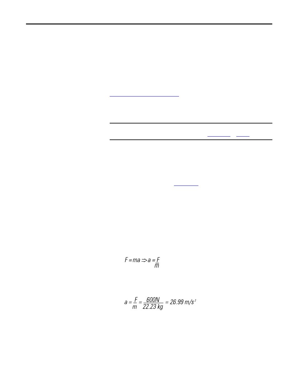
Start with:
Total Moving Mass = m = Payload + Stage Moving Mass
= 10 kg + 10.23 kg = 22.23 kg
So the maximum deceleration rate, Dmax is 26.99 m/s
2
.
IMPORTANT
Bumper stops are not intended as range of motion stops, but they can stop the
moving slide up to the ratings listed in
on
(1) Velocity and kinetic energy can be much higher due to a uncontrolled worst-case motion constrained by the stroke and power
capacity of the motor drive paring only.
(2) Approximation only; actual peak force typically decreases as speed increases.