Junction box connectors – Rockwell Automation CHPS-250 Linear Stage Installation User Manual
Page 37
Rockwell Automation Publication CHPS-UM001D-EN-P - July 2014
37
Connector Data
Chapter 5
Junction Box Connectors
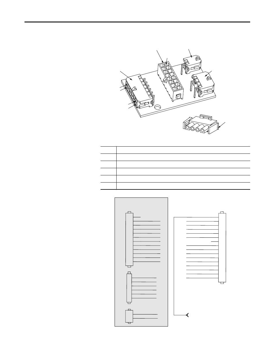
The following diagram and tables identify the power and feedback pinouts of the
junction box connector, use this information to make custom cables
Item Description
A
J1 Feedback connector, output to flex cable, Mating connector is a Molex P/N 43025-1600
B
J2 Thermistor signal connector, the input from side
C
J3 Hall signal connector, input from side
D
J4 Encoder signal connector, input from side
E
Mating power connector AMP 359780-1
Pin 1
9
16
8
Pin 1
7
6
12
Pin 1
4
D
A
B
C
E
Signals from slide
To flexible feedback cable
ENCA+
ENCB+
INDEX+
POSLIM
5V
HALLS3
GND
SHIELD
GND
HALLS2
SHIELD
5V
ENCB-
ENCA-
INDEX-
HALLS1
SHIELD
HALLS3
ENCA+
ENCB+
INDEX+
POSLIM
GND
HALLS1
HALLS2
ENCA-
ENCB-
INDEX-
NEGLIM
5V
TEMP+
NEGLIM
GND
TEMP+
1
2
3
4
5
6
1
2
3
4
5
6
7
8
9
10
11
12
1
2
1
2
3
4
5
6
7
8
9
10
11
12
13
14
15
16
TP1
Shield terminates to mounting hole
J3
Header 2X3, Right Angle
J4
Header 2X6 Right Angle
J2
Header 2, Right Angle
J1
Header 2x8, Vertical