Attaching the ground strap and interface cables – Rockwell Automation CHPS-250 Linear Stage Installation User Manual
Page 40
40
Rockwell Automation Publication CHPS-UM001D-EN-P - July 2014
Chapter 6
Connecting the Stage
Attaching the Ground Strap and Interface Cables
The only electrical connections necessary between the stage and the drive system
are the ground strap and the two cables.
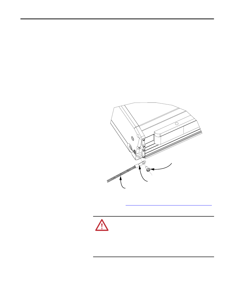
1. For electrical safety, connect the ground screw on the chassis of the stage to
the ground bus for your system.
To reduce the effects of electromagnetic interference (EMI), bond the
stage with a braided ground strap, 12 mm (0.5 in.) wide minimum, to a
grounded metal surface. This creates a low-impedance return path for
high-frequency energy.
2. Torque the ground screw at the stage to 2 N•m (18 lb•in)
3. Form a drip loop in each cable at a point directly before it attaches to the
stage. Refer to the
Connecting Kinetix Type Motor and Feedback Cables
diagram for a visual example.
ATTENTION: Be sure that cables are installed and restrained to
prevent uneven tension or flexing at the cable connectors.
Excessive and uneven lateral force at the cable connectors can result in
the connector’s environmental seal opening and closing as the cable
flexes.
Failure to observe these safety procedures could result in damage to
the motor and its components.
M5 x 0.8 -6H
Ground Screw
Braided Ground Wire 12 mm (0.5 in) min.
Lug