Motor coil resistance measurements, Figure 17 - motor phasing schematic, Motor phasing schematic – Rockwell Automation CHPS-250 Linear Stage Installation User Manual
Page 58
58
Rockwell Automation Publication CHPS-UM001D-EN-P - July 2014
Chapter 8
Troubleshooting
Motor Coil Resistance
Measurements
If a motor coil electrical problem is suspected perform this check.
1. Let the coil attain ambient room temperature, approximately 25 °C
(77 °F).
2. Verify the drive power is OFF.
3. Disconnect all stage leads (phases and ground) from the drive.
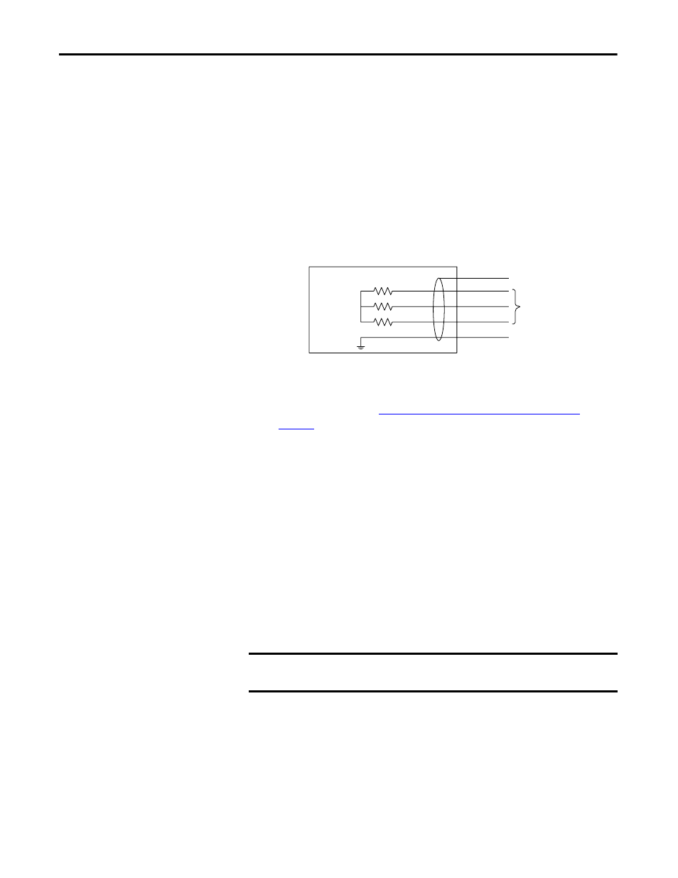
4. Measure the phase-to-phase (ptp) resistance of the phase combinations (U
to V, V to W, and W to U) and record the values.
Verify these three readings are approximately equal to each other.
Figure 17 - Motor Phasing Schematic
Compare the phase resistance readings to the cold resistance specification
of the coil model. See
CHPS-Series Stage Technical Specifications
If the three readings are balanced but vary from the specified reading, the
reason can be a special coil model. Cable resistance can cause the result to
be significantly higher.
5. To rule out the cable resistance, disconnect the stage cable and repeat the
procedure this time at the stage motor power termination at the junction
box.
6. Measure and verify the phase-to-ground resistance for each phase is
>100 MΩ. A lower reading indicates a potential electrical problem.
To rule out a field cable problem disconnect the stage cable and repeat the
procedure this time at stage motor power termination.
If any reading with the cable disconnected is
≤
100 MΩ, consult Rockwell
Automation; the stage can have an internal electrical problem
IMPORTANT
Do not perform coil or insulation electrical stress tests (Megger or Hi-Pot test)
without consulting Rockwell Automation technical support.
Lamination
Frame
R
ptn
R
ptp
U
V
W
Motor Phases
Motor Ground
Shield
R
ptp
= R
ptn
X 2