Motor brake – Rockwell Automation 2097-Vxxx Kinetix 300 EtherNet/IP Indexing Servo Drive User Manual User Manual
Page 33
Rockwell Automation Publication 2097-UM001D-EN-P - November 2012
33
Installing the Kinetix 300 Drive System
Chapter 2
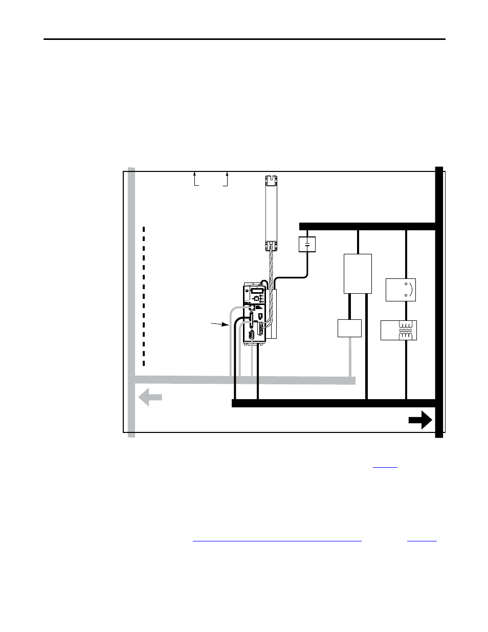
When mounting your shunt module inside the enclosure, follow these additional
guidelines:
• Mount the shunt resistor anywhere in the dirty zone, but as close to the
Kinetix 300 drive as possible.
• Shunt wires can be run with motor power cables.
• Keep unshielded wiring as short as possible. Keep shunt wiring as flat to
the cabinet as possible.
• Separate shunt wires from other sensitive, low-voltage signal cables.
Figure 8 - Shunt Resistor Inside the Enclosure
(1) If drive system I/O cable contains (dirty) relay wires, route cable in dirty wire way.
(2) When space does not permit 150 mm (6.0 in.) clearance, install a grounded steel shield between the drive and clean wireway. For
examples, see the System Design for Control of Electrical Noise Reference Manual, publi
.
Motor Brake
The brake is mounted inside the motor and how you connect to the drive
depends on the motor series.
Kinetix 300 Drive/Rotary Motor Wiring Examples
beginning on
for the interconnect diagram of your drive/motor combination.
Shunt Wiring Methods:
Twisted pair in conduit (first choice).
Shielded twisted pair (second choice).
Twisted pair, two twists per foot (min) (third choice).
Contactor
Dirty Wireway
Very dirty zone
segregated (not in wireway).
Ethernet
(shielded)
Cable
No sensitive
equipment within 150
mm (6.0 in.).
(2)
Route 24V DC I/O
Shielded Cable
24V Motor
Brake PS
Circuit
Breaker
I/O
(1)
, Ethernet, and Feedback
Cables
DC
Filter
Kinetix 300
Drive
Route Encoder/Analog/Registration
Shielded Cables
D
VD
C
I/O
(1)
, Motor Power, and Safety Cables
XFMR
D
D
AC Line
Filter
VD
D
C
Clean Wireway
Enclosure