Shield-contact plate connections, Detailed wiring information – Rockwell Automation 1755-OF8 GuardPLC Controller Systems User Manual
Page 48
48
Publication 1753-UM001C-EN-P - March 2010
Chapter 3 General Wiring Considerations
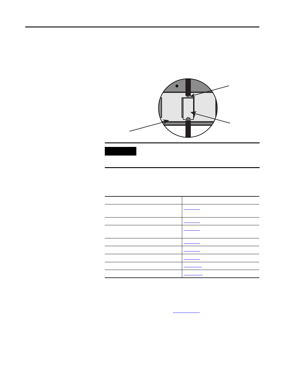
Shield-contact Plate
Connections
Shielded cabling is fed in from below so that the shielding can be
connected to the shield-contact plate by using a clip. Remove about 2
cm (0.79 in.) of the outer cable insulation so that the mesh is exposed
at the point where the cable is clipped to the plate. Position the clip
over the uninsulated cable shielding and push it into the slots of the
shield contact plate until it fits firmly in place, as shown below.
Detailed Wiring
Information
For detailed wiring information by product, see the table below.
To be sure that GuardPLC controllers and I/O modules are used in a
safety-related manner (SIL3 in accordance to IEC 61508), the whole
system, including connected sensors and encoders, must satisfy the
safety requirements described in the GuardPLC Controllers Safety
Reference Manual, publicatio
IMPORTANT
Make sure that the mesh comes in direct contact with the
shield-contact plate. If the mesh does not touch the plate, the
cable is not grounded.
63 64
65
66 67 68
71 72
69 70
net
T
4
Cable Clip
Mesh
Shield-contact Plate
For
See
GuardPLC 1600, GuardPLC 1800 and
GuardPLC 1200 Controllers
GuardPLC 2000 Controller
1753-IB16, 1753-OB16, 1753-IB20XOB8
Modules
1753-IB8XOB8
1753-IB16XOB8
1753-IF8XOF4
1753-OW8
Wiring Examples
- 1755-HSC GuardPLC Controller Systems 1755-IF8 GuardPLC Controller Systems 1755-IB24XOB16 GuardPLC Controller Systems 1755-A6 GuardPLC Controller Systems 1755-L1 GuardPLC Controller Systems 1754-L28BBB GuardPLC Controller Systems 1753-IB20XOB8 GuardPLC Controller Systems 1753-OB16 GuardPLC Controller Systems 1753-IB16 GuardPLC Controller Systems 1753-L32BBBP-8A GuardPLC Controller Systems 1753-L32BBBM-8A GuardPLC Controller Systems 1753-L28BBBP GuardPLC Controller Systems 1753-L28BBBM GuardPLC Controller Systems