Rockwell Automation 1755-OF8 GuardPLC Controller Systems User Manual
Page 218
218
Publication 1753-UM001C-EN-P - March 2010
Chapter 19 Use GuardPLC Controller as an Adapter
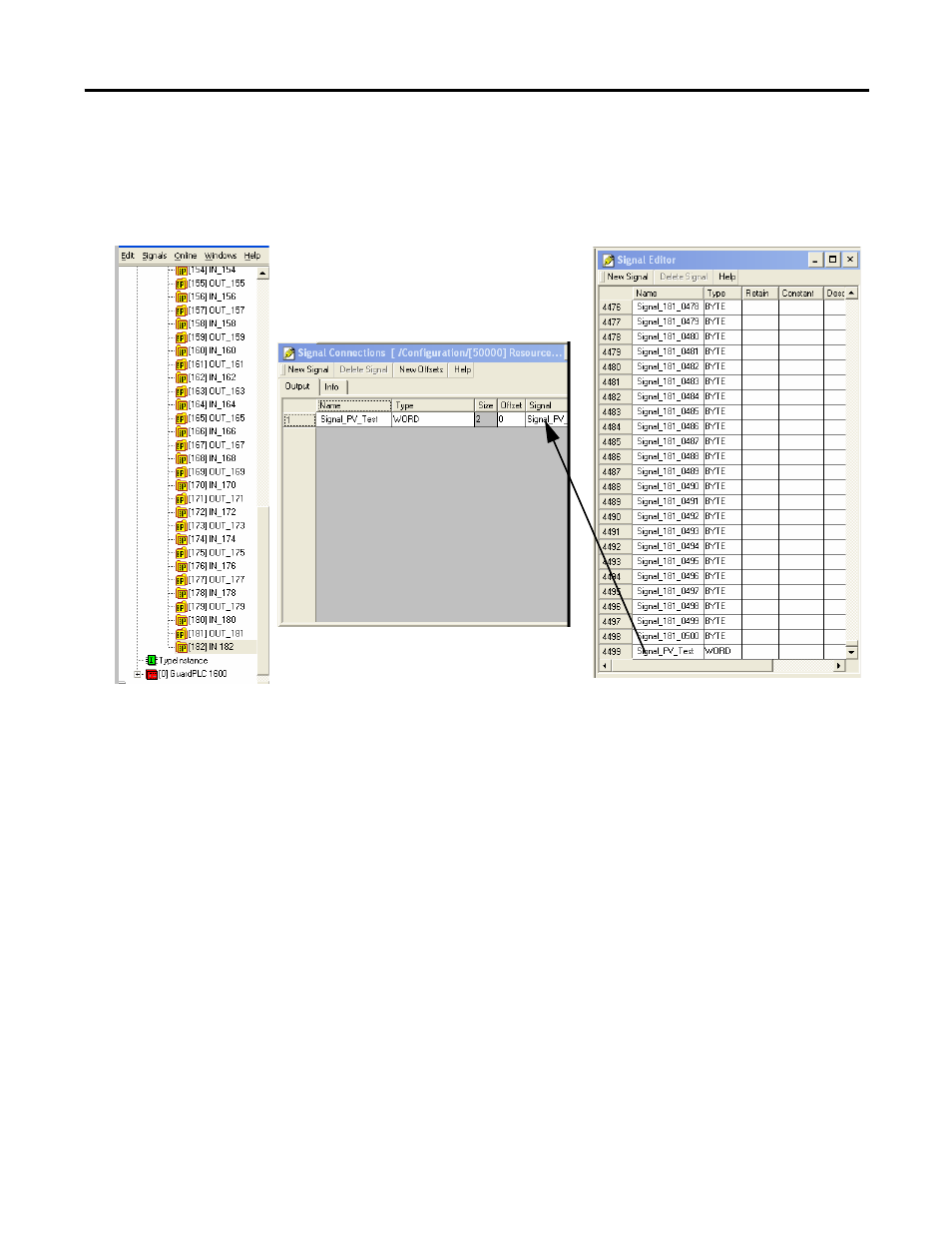
The example below shows the Signal Connections dialog box
for an input assembly. Signals created in the Signal Editor are
assigned to connections to the Output tab for the input
assembly.
2. Drag the signals from the Signal Editor to the Signal Connections
tab.
3. After assigning the signals, either assign the offsets manually or
click New Offsets and choose Renumber at the Renumber
Offsets prompt.
The offsets are byte offsets.
When assigning offsets manually, make sure there are no holes
in the assembly buffer and that the next signal starts where the
previous signal ended.
If the scanner is a Logix controller, be sure that:
•
the Run/Idle header is checked for output assemblies.
•
the Run/Idle header is unchecked for input assemblies.
•
output assemblies have 4 extra bytes in the beginning to hold
the Run/Idle header. These can be 1 DWORD or 2 WORD or
4 byte signals.
- 1755-HSC GuardPLC Controller Systems 1755-IF8 GuardPLC Controller Systems 1755-IB24XOB16 GuardPLC Controller Systems 1755-A6 GuardPLC Controller Systems 1755-L1 GuardPLC Controller Systems 1754-L28BBB GuardPLC Controller Systems 1753-IB20XOB8 GuardPLC Controller Systems 1753-OB16 GuardPLC Controller Systems 1753-IB16 GuardPLC Controller Systems 1753-L32BBBP-8A GuardPLC Controller Systems 1753-L32BBBM-8A GuardPLC Controller Systems 1753-L28BBBP GuardPLC Controller Systems 1753-L28BBBM GuardPLC Controller Systems