Create ladder logic – Rockwell Automation 1755-OF8 GuardPLC Controller Systems User Manual
Page 230
230
Publication 1753-UM001C-EN-P - March 2010
Chapter 19 Use GuardPLC Controller as an Adapter
5. Add a ReadBuffer tag with type DINT[3] and a WriteBuffer tag
with type SINT[4].
These types correspond directly to the signal types of the
GuardPLC adapter assemblies. When explicit CIP messaging is
used to read and write assemblies, the tag being written to or
read from must be of the same or larger size than the assembly
size in the GuardPLC controller. The tag types should match the
signal types associated with the target assembly in RSLogix
Guard PLUS! software.
For more information on programming Logix controllers, refer to
the Logix5000 Controllers Common Procedures Programming
Manual, publicatio
Create Ladder Logic
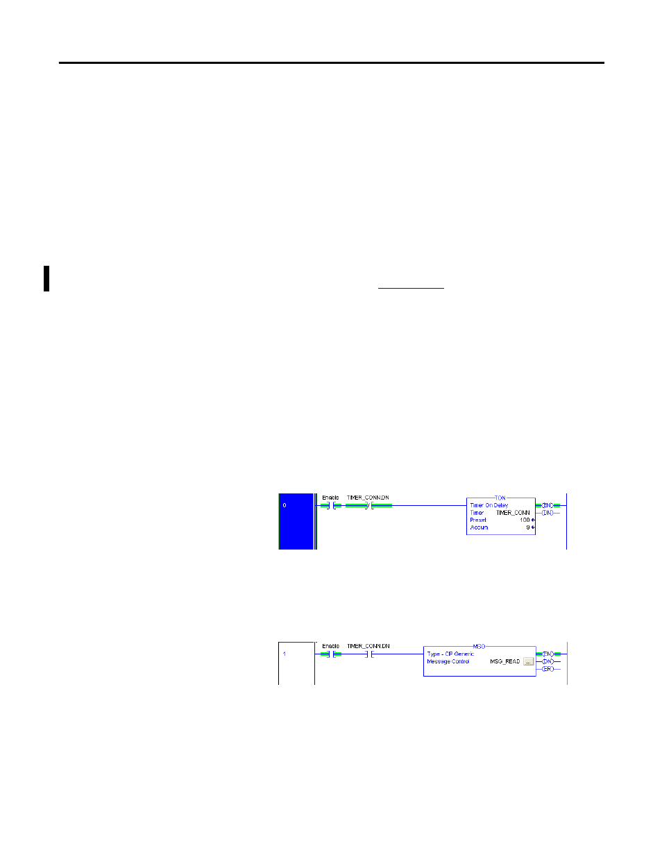
1. Switch to the Main Routine window in RSLogix 5000 software.
2. Build the first rung containing the following instructions:
•
Examine On Enable tag to start the connected messaging.
•
Examine Off TIMER_CONN.DN.
•
A timer instruction with the control tag TIMER_CONN and a
preset of 100. This is the rate at which Class 3 messages are
sent by the Logix controller.
3. Build the second run containing the following instructions:
•
Examine On Enable tag.
•
Examine On TIMER_CONN.DN.
•
Message instruction with the control tag MSG_READ.
- 1755-HSC GuardPLC Controller Systems 1755-IF8 GuardPLC Controller Systems 1755-IB24XOB16 GuardPLC Controller Systems 1755-A6 GuardPLC Controller Systems 1755-L1 GuardPLC Controller Systems 1754-L28BBB GuardPLC Controller Systems 1753-IB20XOB8 GuardPLC Controller Systems 1753-OB16 GuardPLC Controller Systems 1753-IB16 GuardPLC Controller Systems 1753-L32BBBP-8A GuardPLC Controller Systems 1753-L32BBBM-8A GuardPLC Controller Systems 1753-L28BBBP GuardPLC Controller Systems 1753-L28BBBM GuardPLC Controller Systems