Quality – Rockwell Automation 1755-OF8 GuardPLC Controller Systems User Manual
Page 37
Publication 1753-UM001C-EN-P - March 2010
37
Installation Chapter 2
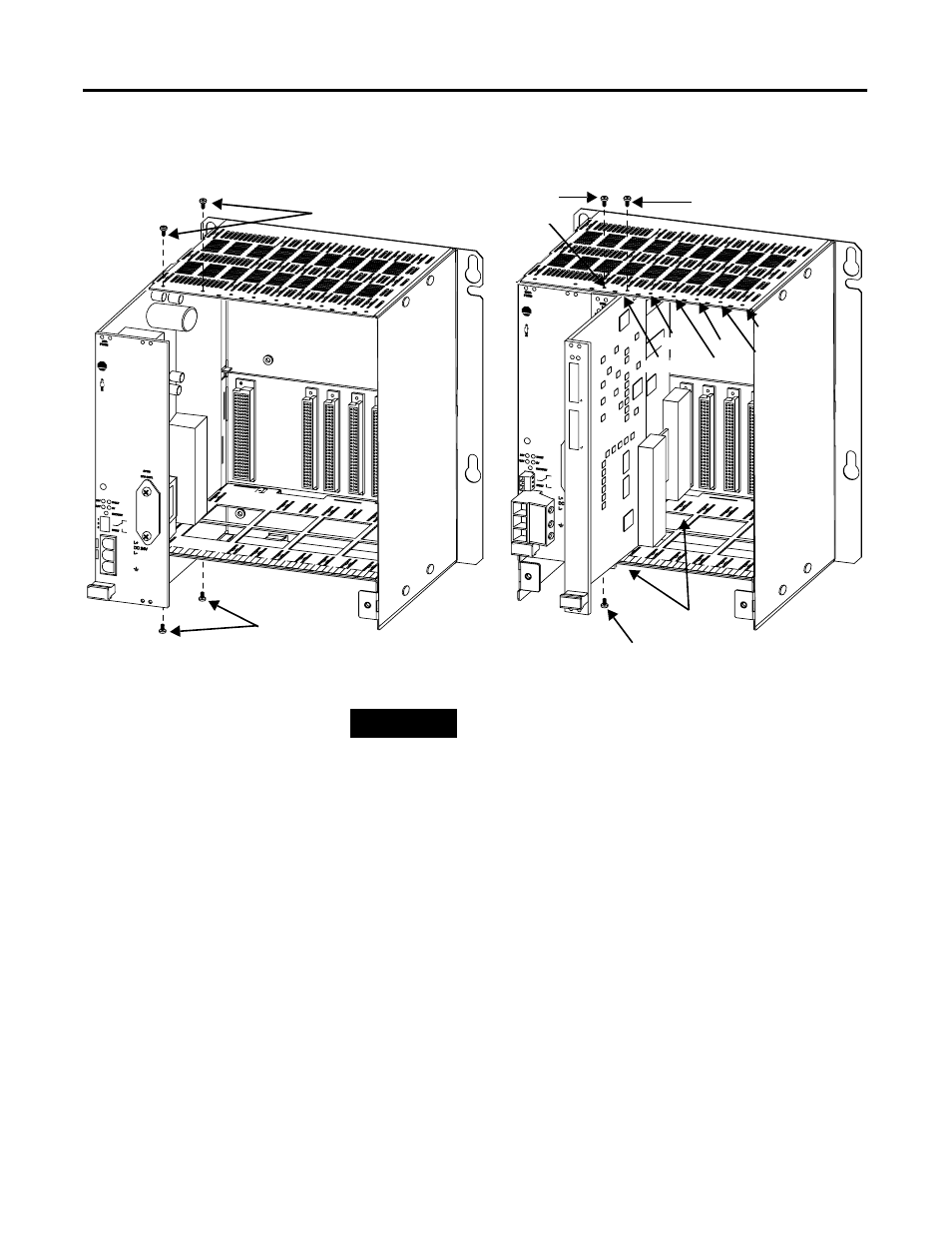
6. Secure the device with the screws on the top and bottom of the
device (see the figure below).
7. Reconnect the fans.
8. Replace the lower panel of the chassis, sliding it over the tabs on
the sides of the chassis and under the tabs on the back of the
chassis.
9. Use the grounding grill screws to attach the grounding grill.
2000
1755-
IF8
1
2
3
4
5
6
7
8
9
10
11
12
13
14
15
16
17
18
RUN
ERR
I-
I2+
I-
I3+
I-
I4+
I-
I1+
I-
I6+/2-
I-
I7+/3-
I-
I8+/4-
I-
I5+/1-
Guard
PLC
Allen-Br
adley
A-B
QUALITY
Guard
PLC
2000
Allen-Br
adley
A-B
QUALITY
I/O Module Screw
I/O Module Screw
Guides
Slot 1
Slot 2
Slot 3
Slot 4
Slot 5
Slot 6
Controller Screw
Power Supply Screws
Slot 0
Power Supply Screws
TIP
If you are installing other GuardPLC 2000 modules, follow their
installation instructions up to this point before you complete the
next 3 steps.
- 1755-HSC GuardPLC Controller Systems 1755-IF8 GuardPLC Controller Systems 1755-IB24XOB16 GuardPLC Controller Systems 1755-A6 GuardPLC Controller Systems 1755-L1 GuardPLC Controller Systems 1754-L28BBB GuardPLC Controller Systems 1753-IB20XOB8 GuardPLC Controller Systems 1753-OB16 GuardPLC Controller Systems 1753-IB16 GuardPLC Controller Systems 1753-L32BBBP-8A GuardPLC Controller Systems 1753-L32BBBM-8A GuardPLC Controller Systems 1753-L28BBBP GuardPLC Controller Systems 1753-L28BBBM GuardPLC Controller Systems