Safe states, Guardplc system hardware, Inputs outputs – Rockwell Automation 1755-OF8 GuardPLC Controller Systems User Manual
Page 21: Guardplc 1200 system, Inputs, Outputs
Publication 1753-UM001C-EN-P - March 2010
21
Overview of Safety Controllers Chapter 1
Safe States
Inputs
The safe state of an input is indicated by a 0 signal being passed to
the user program logic. When a fault occurs, the inputs are switched
off (0).
Outputs
An output is in the safe state when it is de-energized. In the event of a
fault, all outputs are switched off. This includes faults in Ethernet
communication.
GuardPLC System
Hardware
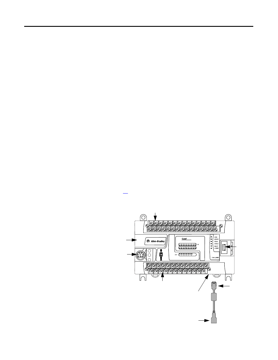
GuardPLC 1200 System
The GuardPLC 1200 controller is a compact system consisting of a
CPU, watchdog, and on-board digital I/O. The GuardPLC 1200
controller features 20 digital inputs, 8 digital outputs, and 2
high-speed counters. An RS-232 serial port supports ASCII
communication and an Ethernet port provides safety-related
communication. A user-supplied 24V DC power supply is required.
See page
for power supply connections.
GuardPLC 1200 Controller
PLC
1200
Ethernet Port
(on Bottom of Controller)
Port for
Factory
Use Only
Upper Terminal Block
Back-up Battery
Compartment
ASCII Serial Port
Lower Terminal Block
Ethernet Dongle
Required
RJ-45 Port
- 1755-HSC GuardPLC Controller Systems 1755-IF8 GuardPLC Controller Systems 1755-IB24XOB16 GuardPLC Controller Systems 1755-A6 GuardPLC Controller Systems 1755-L1 GuardPLC Controller Systems 1754-L28BBB GuardPLC Controller Systems 1753-IB20XOB8 GuardPLC Controller Systems 1753-OB16 GuardPLC Controller Systems 1753-IB16 GuardPLC Controller Systems 1753-L32BBBP-8A GuardPLC Controller Systems 1753-L32BBBM-8A GuardPLC Controller Systems 1753-L28BBBP GuardPLC Controller Systems 1753-L28BBBM GuardPLC Controller Systems