Rockwell Automation 1755-OF8 GuardPLC Controller Systems User Manual
Page 221
Publication 1753-UM001C-EN-P - March 2010
221
Use GuardPLC Controller as an Adapter Chapter 19
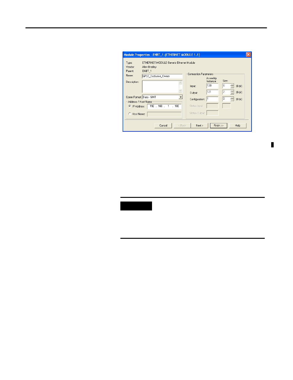
Exclusive Owner
To establish an exclusive owner connection, follow these steps.
1. Choose Data — SINT in the Comm Format Field.
2. Type the GuardPLC controller’s Input Assembly instance number
in the Input Assembly Instance field.
3. Type the size of the Input Assembly in the Input Size field.
4. Type the GuardPLC controller’s Output Assembly instance
number in the Output Assembly Instance field.
5. Type the size of the Output Assembly minus 4 bytes in the
Output Size field.
The data size in RSLogix 5000 software does not include the
4 bytes of the Run/Idle header, but these 4 bytes must be part of
the GuardPLC controller’s output assembly, because the
ControlLogix controller sends the 4-byte Run/Idle header to the
GuardPLC controller.
For example, if you created an output assembly of 6 bytes (6
BYTE signals assigned in RSLogix Guard PLUS! software), you
must enter an Output Size of 2 in RSLogix 5000 software,
because only the last 2 bytes contain the actual data.
IMPORTANT
This entry must exactly match the size of the input
assembly, or the GuardPLC adapter controller will return
an error.
The size of the input assembly is determined during the
signal connection process.
- 1755-HSC GuardPLC Controller Systems 1755-IF8 GuardPLC Controller Systems 1755-IB24XOB16 GuardPLC Controller Systems 1755-A6 GuardPLC Controller Systems 1755-L1 GuardPLC Controller Systems 1754-L28BBB GuardPLC Controller Systems 1753-IB20XOB8 GuardPLC Controller Systems 1753-OB16 GuardPLC Controller Systems 1753-IB16 GuardPLC Controller Systems 1753-L32BBBP-8A GuardPLC Controller Systems 1753-L32BBBM-8A GuardPLC Controller Systems 1753-L28BBBP GuardPLC Controller Systems 1753-L28BBBM GuardPLC Controller Systems