Guardplc 2000 controller, i/o, and power supply – Rockwell Automation 1755-OF8 GuardPLC Controller Systems User Manual
Page 36
36
Publication 1753-UM001C-EN-P - March 2010
Chapter 2 Installation
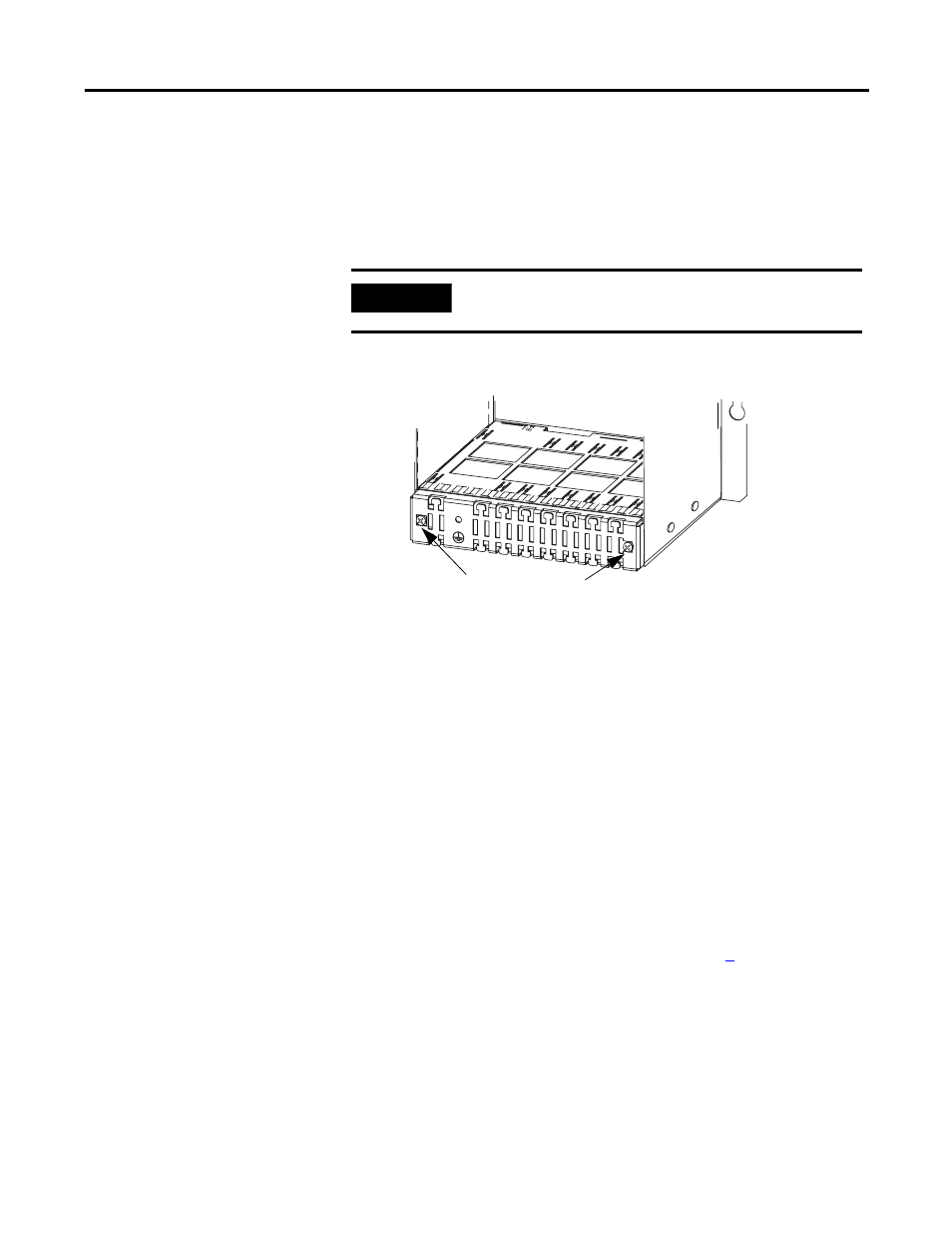
GuardPLC 2000 Controller, I/O, and Power Supply
Mount the GuardPLC 2000 chassis prior to installing the controller,
I/O, and power supply.
1. Before you insert the device, you must detach the grounding
grill. To do this, remove the grounding grill screws.
2. Remove the lower panel of the chassis and disconnect the fans.
3. Power Supply: Insert the power supply into the leftmost slot of
the chassis.
Controller: Insert the controller into the slot directly to the right
of the power supply module (slot 0).
I/O Module: Insert the module into any unused slot from 1…6
(see the figure below). Keep the module in line with the guides
so the module runs smoothly in the track.
4. Begin pushing the device into the chassis.
a. If there is resistance when you push the device into the
backplane, do not force the device because the pins will
bend.
b. Remove the device and start again at step
5. Continue pushing the device into the chassis until the front of
the device is flush with the other modules in the chassis.
IMPORTANT
Disconnect the power supply, 1755-PB720, from the 24V DC
supply voltage before you insert any I/O modules.
grounding grill screws
- 1755-HSC GuardPLC Controller Systems 1755-IF8 GuardPLC Controller Systems 1755-IB24XOB16 GuardPLC Controller Systems 1755-A6 GuardPLC Controller Systems 1755-L1 GuardPLC Controller Systems 1754-L28BBB GuardPLC Controller Systems 1753-IB20XOB8 GuardPLC Controller Systems 1753-OB16 GuardPLC Controller Systems 1753-IB16 GuardPLC Controller Systems 1753-L32BBBP-8A GuardPLC Controller Systems 1753-L32BBBM-8A GuardPLC Controller Systems 1753-L28BBBP GuardPLC Controller Systems 1753-L28BBBM GuardPLC Controller Systems