Rockwell Automation 1755-OF8 GuardPLC Controller Systems User Manual
Page 211
Publication 1753-UM001C-EN-P - March 2010
211
Introduction to EtherNet/IP Communication Chapter 18
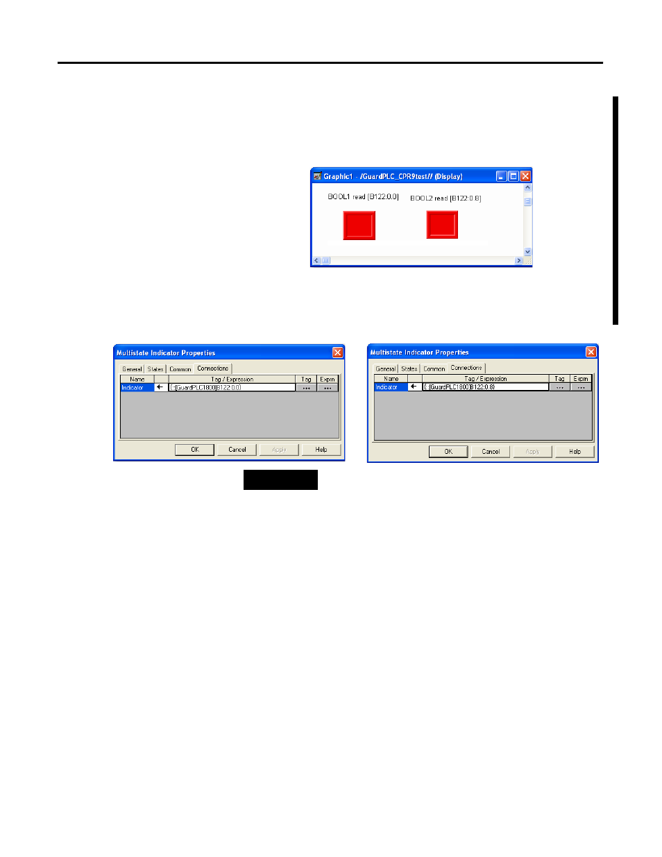
The multistate indicator objects shown below read the two BOOLs
from the GuardPLC controller. Tags B122:0 and B122:1 were used to
match the input assembly used in the GuardPLC controller. The
GuardPLC controller does not use the ‘B’; it is required for FactoryTalk
View software.
B122:0.0 corresponds to the first BOOL tag in the GuardPLC assembly
122. B122:0.8 corresponds to the second BOOL tag in the GuardPLC
assembly 122.
TIP
GuardPLC is a BYTE machine. BOOL tags take up a complete
BYTE in the buffer. That is why .0 and .8 are used in the VIEW
tags to read the first bit from the GuardPLC byte. If a third BOOL
tag was read, the address in the VIEW tag would be B122:1.0.
- 1755-HSC GuardPLC Controller Systems 1755-IF8 GuardPLC Controller Systems 1755-IB24XOB16 GuardPLC Controller Systems 1755-A6 GuardPLC Controller Systems 1755-L1 GuardPLC Controller Systems 1754-L28BBB GuardPLC Controller Systems 1753-IB20XOB8 GuardPLC Controller Systems 1753-OB16 GuardPLC Controller Systems 1753-IB16 GuardPLC Controller Systems 1753-L32BBBP-8A GuardPLC Controller Systems 1753-L32BBBM-8A GuardPLC Controller Systems 1753-L28BBBP GuardPLC Controller Systems 1753-L28BBBM GuardPLC Controller Systems