Rockwell Automation 1755-OF8 GuardPLC Controller Systems User Manual
Page 234
234
Publication 1753-UM001C-EN-P - March 2010
Chapter 19 Use GuardPLC Controller as an Adapter
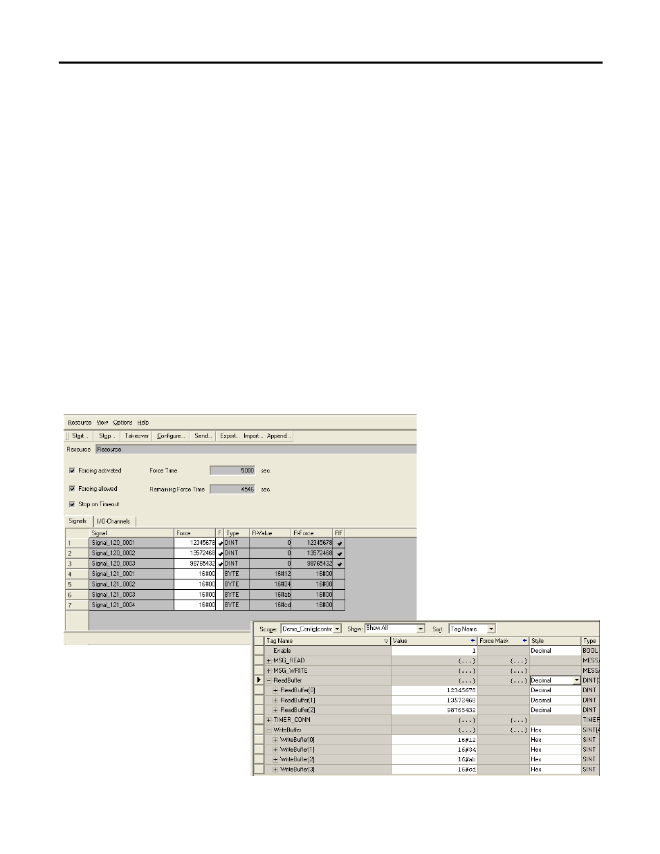
2. Set the WriteBuffer display type to Hex. Enter 16#12, 16#34,
16#ab, 16#cd in the WriteBuffer.
3. Set the ReadBuffer type to Decimal.
The ReadBuffer is set to Decimal because RSLogix Guard PLUS!
software displays DINT types in decimal format only.
4. Configure the Force Editor menu in RSLogix Guard PLUS!
software to display all signals for assemblies IN_120 and
OUT_121.
5. Set signals for the IN_120 assembly to values 12345678,
13572468, 98765432.
6. Start forcing to send the new signal values.
7. Verify that RSLogix 5000 software displays the same values in
the ReadBuffer.
8. Verify that the OUT_121 signals show 16#12, 16#34, 16#ab,
16#cd.
This manual is related to the following products:
- 1755-HSC GuardPLC Controller Systems 1755-IF8 GuardPLC Controller Systems 1755-IB24XOB16 GuardPLC Controller Systems 1755-A6 GuardPLC Controller Systems 1755-L1 GuardPLC Controller Systems 1754-L28BBB GuardPLC Controller Systems 1753-IB20XOB8 GuardPLC Controller Systems 1753-OB16 GuardPLC Controller Systems 1753-IB16 GuardPLC Controller Systems 1753-L32BBBP-8A GuardPLC Controller Systems 1753-L32BBBM-8A GuardPLC Controller Systems 1753-L28BBBP GuardPLC Controller Systems 1753-L28BBBM GuardPLC Controller Systems