Terminal connections, Guardplc 2000 chassis, Terminals accommodate wire sizes up to 1.5 mm – Rockwell Automation 1755-OF8 GuardPLC Controller Systems User Manual
Page 47: 16 awg) for input/output wiring and up to 2.5 mm, 14 awg) for voltage supply connections
Publication 1753-UM001C-EN-P - March 2010
47
General Wiring Considerations Chapter 3
GuardPLC 1600 and GuardPLC 1800 Controllers and Distributed I/O
The I/O module is functionally grounded through its DIN rail
connection. A protective earth ground connection is required and is
provided by a separate grounding screw, located on the upper left of
the housing and marked with the grounding symbol
.
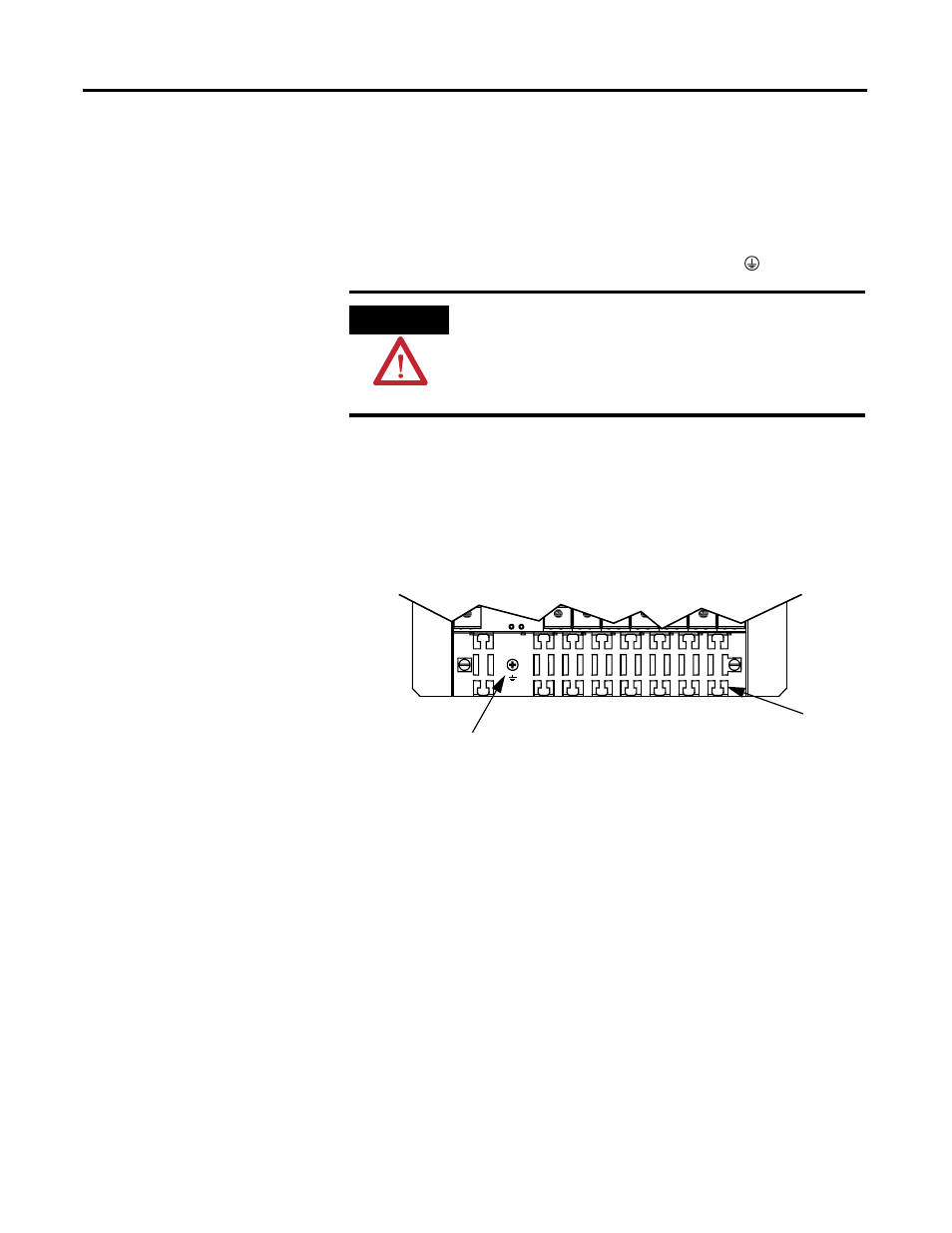
GuardPLC 2000 Chassis
Ground the GuardPLC 2000 chassis and cables by using the grounding
screw located on the left side of the grounding grill. Ground the
chassis via the grounding grill.
Terminal Connections
Terminals accommodate wire sizes up to 1.5 mm
2
(16 AWG) for
input/output wiring and up to 2.5 mm
2
(14 AWG) for voltage supply
connections.
ATTENTION
This product is grounded through the DIN rail to chassis ground.
Use zinc plated yellow-chromate steel DIN rail to assure proper
grounding. The use of other DIN rail materials (for example,
aluminum and plastic) that can corrode, oxidize, or are poor
conductors, can result in improper or intermittent grounding.
CPU
DIO
AI
AO
CO
PS
DIO
CO
Grounding Screw
Grounding Grill
- 1755-HSC GuardPLC Controller Systems 1755-IF8 GuardPLC Controller Systems 1755-IB24XOB16 GuardPLC Controller Systems 1755-A6 GuardPLC Controller Systems 1755-L1 GuardPLC Controller Systems 1754-L28BBB GuardPLC Controller Systems 1753-IB20XOB8 GuardPLC Controller Systems 1753-OB16 GuardPLC Controller Systems 1753-IB16 GuardPLC Controller Systems 1753-L32BBBP-8A GuardPLC Controller Systems 1753-L32BBBM-8A GuardPLC Controller Systems 1753-L28BBBP GuardPLC Controller Systems 1753-L28BBBM GuardPLC Controller Systems