19 - use guardplc controller as an adapter, Introduction, Configure the guardplc controller as an adapter – Rockwell Automation 1755-OF8 GuardPLC Controller Systems User Manual
Page 215: Chapter 19, Use guardplc controller as an adapter, Configure the adapter input assembly, Chapter
215
Publication 1753-UM001C-EN-P - March 2010
215
Chapter
19
Use GuardPLC Controller as an Adapter
Introduction
Configure the GuardPLC
Controller as an Adapter
Make sure the GuardPLC controller resource has the EtherNet/IP
protocol added under the Protocols folder in the RSLogix Guard PLUS!
Hardware Management project tree. If it does not, see page
for
instructions on adding EtherNet/IP protocol.
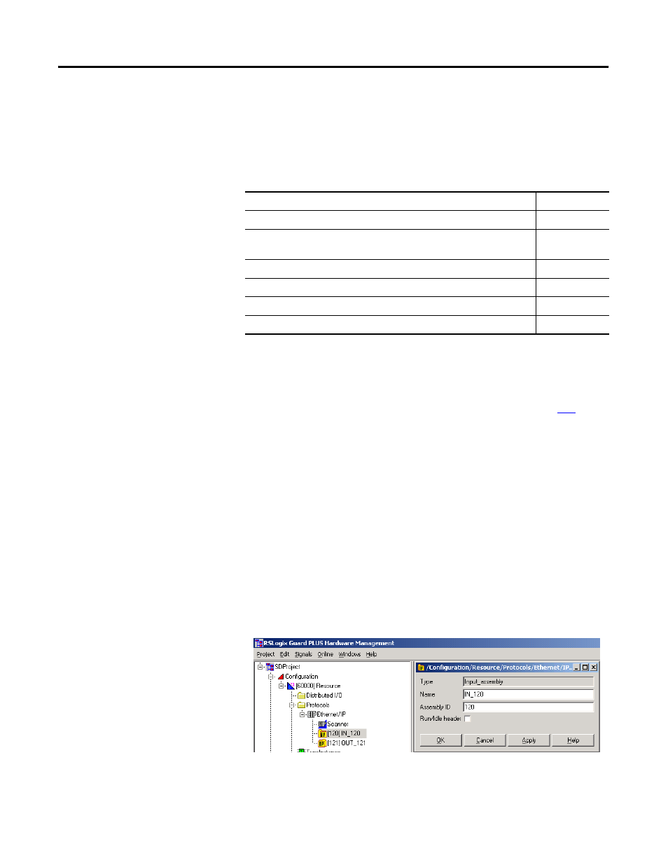
Configure the Adapter Input Assembly
Input assemblies contain data that is produced by the GuardPLC
controller and consumed by a scanner.
1. You can use the default input assembly IN_120 or create a new
input assembly by right-clicking EtherNet/IP in the project tree
and choosing New > Input Assembly.
2. Modify the input assembly properties, if desired, by
right-clicking the input assembly and choosing Properties.
Topic
Page
Configure the GuardPLC Controller as an Adapter
Open a Class 1 Connection from a Logix Controller to the GuardPLC
Controller
Open a Class 3 Connection from a Logix Controller
Use a GuardPLC Controller as an Unconnected Adapter
Use Unconnected PCCC Messaging from a PLC-5 or SLC 5/05 Controller 235
Use Unconnected CIP Messaging from a PanelView Standard Terminal
- 1755-HSC GuardPLC Controller Systems 1755-IF8 GuardPLC Controller Systems 1755-IB24XOB16 GuardPLC Controller Systems 1755-A6 GuardPLC Controller Systems 1755-L1 GuardPLC Controller Systems 1754-L28BBB GuardPLC Controller Systems 1753-IB20XOB8 GuardPLC Controller Systems 1753-OB16 GuardPLC Controller Systems 1753-IB16 GuardPLC Controller Systems 1753-L32BBBP-8A GuardPLC Controller Systems 1753-L32BBBM-8A GuardPLC Controller Systems 1753-L28BBBP GuardPLC Controller Systems 1753-L28BBBM GuardPLC Controller Systems