Rockwell Automation 1336T PLC Comm. Adapter, Series B, FRN 2.xx-3.xx User Manual
Page 78
5–4
Publication 1336 FORCE–5.13 –– September, 1998
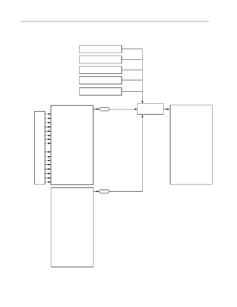
The following figure shows the correlation between the output image
table bits and the bits used by the Logic Command.
Bit 0
Bit 1
Bit 2
Bit 3
Bit 4
Bit 5
Bit 6
Bit 7
Bit 10
Bit 11
Bit 12
Bit 13
Bit 14
Bit 15
Bit 16
Bit 17
Logic Command –– Parameter 52
Bit 0
Ramp Stop
Bit 1
Start
Bit 2
Jog 1
Bit 3
Clear Fault
Bit 4
Forward
Bit 5
Reverse
Bit 6
Jog 2
Bit 7
Current Limit Stop
Bit 8
Coast Stop
Bit 9
Ramp Disable
Bit 10
Flux Enable
Bit 11
Process Trim Enable
Bit 12
Velocity Ref Select A
Bit 13
Velocity Ref Select B
Bit 14
Velocity Ref Select C
Bit 15
Reset Drive
Channel A –– Parameter 367
Bit 0
Ramp Stop
Bit 1
Start
Bit 2
Jog 1
Bit 3
Clear Fault
Bit 4
Forward
Bit 5
Reverse
Bit 6
Jog 2
Bit 7
Current Limit Stop
Bit 8
Coast Stop
Bit 9
Ramp Disable
Bit 10
Flux Enable
Bit 11
Process Trim Enable
Bit 12
Velocity Ref Select A
Bit 13
Velocity Ref Select B
Bit 14
Velocity Ref Select C
Bit 15
Reset Drive
Channel B –– Parameter 368
Bit 0
Ramp Stop
Bit 1
Start
Bit 2
Jog 1
Bit 3
Clear Fault
Bit 4
Forward
Bit 5
Reverse
Bit 6
Jog 2
Bit 7
Current Limit Stop
Bit 8
Coast Stop
Bit 9
Ramp Disable
Bit 10
Flux Enable
Bit 11
Process Trim Enable
Bit 12
Velocity Ref Select A
Bit 13
Velocity Ref Select B
Bit 14
Velocity Ref Select C
Bit 15
Reset Drive
SCANport 5
SCANport 4
SCANport 3
SCANport 2
SCANport 1
368
ChB Logic Cmd In
367
ChA Logic Cmd In
Logic Evaluation
Block
Output Image
Parameter
(such as 323)
in octal